S0 Interface Module
digital Link
digital Link
PCX
UAI Board
(or MIX Board)
Digital set
to Mains
(Option)
S0 set
S0 Bus
S0 Terminal
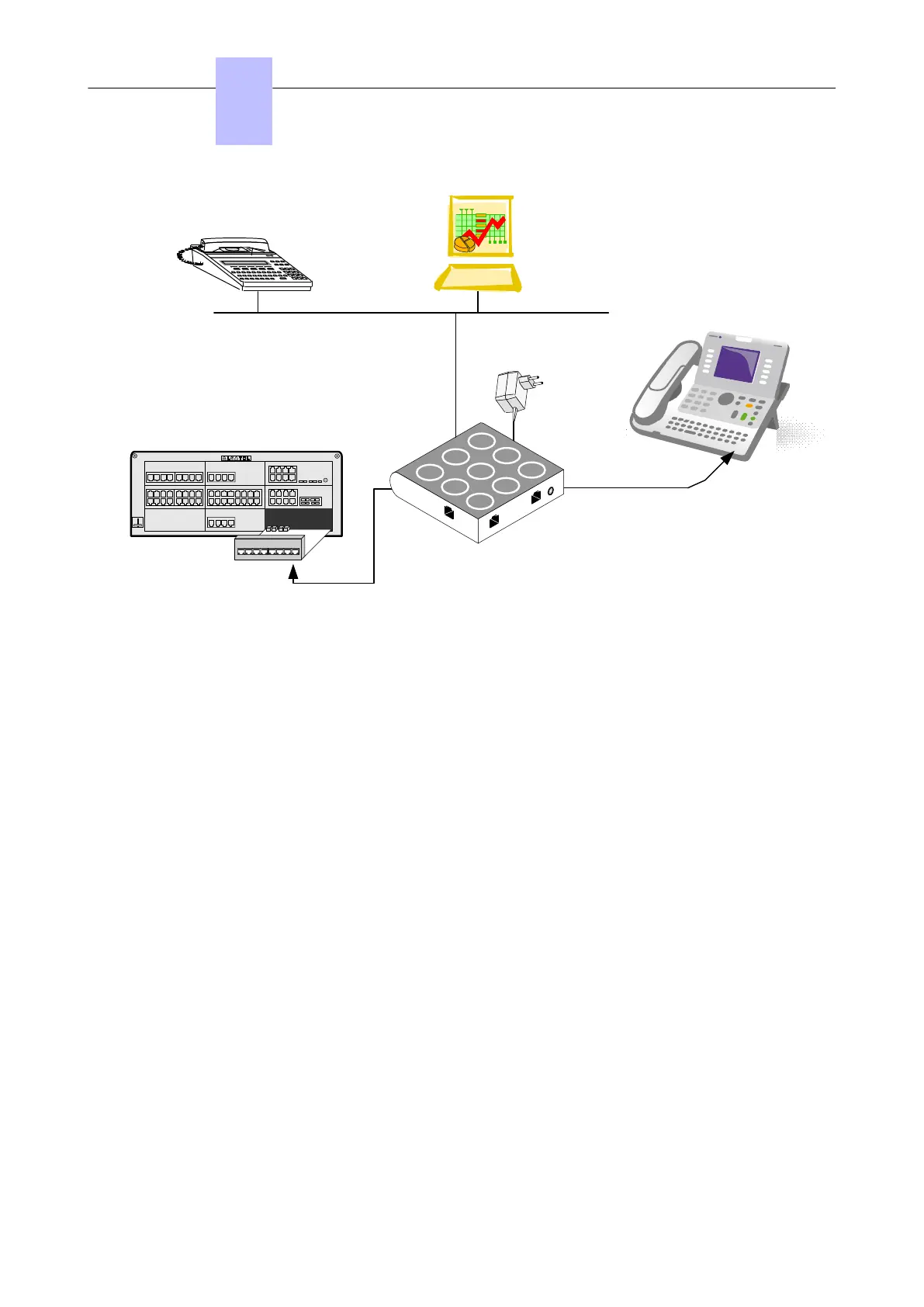
Figure 4.18: Example of Configuration with an S0 Interface Module
The S0 module provides an S0 bus supplying power. An external power supply (230V AC/48V DC
adapter) is required.
There are two possible operating modes on the S0 bus:
• Non permanent layer: layer 1 must be set up by the calling end (PCX or terminal) at the start of
each call; layer 1 is shut down at the end of the call
• Permanent layer: operation of the S0 bus depends on the direction in which the initial call was set
up:
• If the call was set up from the PCX to the terminal, layer 1 is kept when the call ends.
• If the call was set up from the terminal to the PCX, layer 1 is shut down at the end of the call. It
must be set up again for the following call. If operation is incompatible with the terminal used,
there are two possible solutions: Either layer 2 is kept, this prevents layer 1 being shut down, or,
layer 1 is set up from the PCX by making a call to the terminal. The call does not need to get
through.
4.12.1.2 Compliant Standards
4.12.1.2.1 Safety Requirements
• EN60950: European requirements
• UL 1950: US requirements
• CAN/CSA-C22.2 No 950-95: Canada
4.12.1.2.2 ECM
• EN55022: Limits and methods of measurement of radio interference characteristics of information
technology equipment
• EN55024: Limits and methods of measurement of immunity characteristics of information
technology equipment
• FCC part15: US requirements
Chapter
4
Installation and Cabling
3EH21123USAA - Ed. 01 - April 2017 - Installation Manual 118/207
 Loading...