• Humidity: the humidity must be in the range 10% - 80% (no condensation) with a maximum
variation of 10% per hour.
• Storage
• Temperature: the temperature must be kept between -20 and +70 degrees Celsius.
• Humidity: the humidity must be kept in the range 10 - 95% (no condensation).
4.1.2.2 Vibration
No vibration, even intermittent, may be transmitted to the equipment when running.
4.1.2.3 Site
• Choose a dry, clean and well ventilated location.
• Maintain an ambient air flow to ensure normal ventilation. If the air flow is blocked or restricted, of
the incoming air is too hot, overheating is possible.
• When installing the equipment in an enclosed 19" rack, verify that the rack is provided with a fan
suited to the heat dissipation of the equipment installed. Maintain a minimum gap of 3 cm around
the side ventilation holes (left and right sides), and of 10 cm minimum around the ventilation holes
at the rear of the equipment. Verify that the air flow is not impeded on the sides of the rack.
• When fixing the system directly to the wall using the wall-mounting kit (OXO Connect S and OXO
Connect M platforms only), maintain a free space of at least 15 cm around the whole system.
Ensure that no objects are placed on the upper part of the system to restrict the extraction of hot air.
When installing several platforms, it is preferable to align then horizontally. When superposing them
vertically, they should be separated by at least 10 cm.
• Verify that the cables connecting the OXO Connect or other equipment, or the supports for the
housing structure (19" rack for example) do not obstruct the air flow through the platform.
• A switchable 230 V or 110 V mains socket (according to country) - 50Hz (LNE) is required at less
than 1 m from the platform unless it is installed in a rack in which case the integrated circuit breaker
is used.
• Adequate lighting must be provided.
4.2 Connections and Cabling
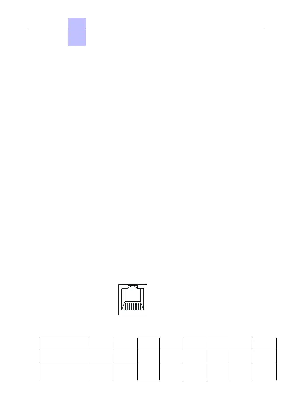
4.2.1 Output Connectors
All outputs are made using Female RJ45 connectors.
1
2345678
Front panel RJ45 female connector
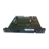
4.2.1.1 PowerCPU EE Board
RJ45 pin 1 2 3 4 5 6 7 8
LAN TX+ TX- RX+ RX-
SLI1/SLI2 Ground +12 V
CenRg
A
ZA1 ZB1
CenRG
B
ZA2 ZB2
Chapter
4
Installation and Cabling
3EH21123USAA - Ed. 01 - April 2017 - Installation Manual 47/207
 Loading...