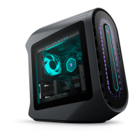
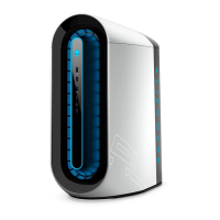
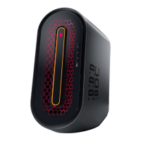
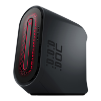
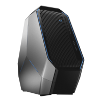
Do you have a question about the Alienware Aurora R9 and is the answer not in the manual?
Guidelines to protect your computer from potential damage and ensure personal safety.
Measures to prevent damage from static electricity to sensitive components.
Details the essential parts included in a standard ESD field service kit.
Diagram identifying key internal components of the computer.
Step-by-step instructions for detaching the left side panel of the computer.
Step-by-step instructions for reattaching the left side panel of the computer.
Procedure for removing the top panel of the computer chassis.
Instructions for detaching the right side panel of the computer.
Steps to safely remove a 2.5-inch hard drive from its bay.
Instructions for removing a 3.5-inch hard drive from the computer.
Procedure to detach the 2.5-inch hard drive mounting cage.
Procedure to detach the 3.5-inch hard drive mounting cage.
Instructions for removing the 460W power supply unit from the chassis.
Instructions for removing the 850W power supply unit from the chassis.
Procedure to detach the right side lighting component from the chassis.
Steps to detach the processor liquid-cooling system from the motherboard.
Procedure to remove the coin-cell battery from the system board.
Instructions for safely removing RAM modules from the memory slots.
Steps to safely remove an M.2 solid-state drive from its slot.
Procedure to remove a single graphics card from its PCIe slot.
Procedure to remove dual graphics cards from their PCIe slots.
Instructions for detaching the front panel of the computer chassis.
Procedure to detach the top bezel from the computer chassis.
Procedure to detach the bottom cover from the computer chassis.
Steps to detach the processor fan and heat-sink assembly from the system board.
Procedure to remove the CPU from its socket on the system board.
Procedure to install the CPU into its socket on the system board.
Procedure to detach the wireless network card from its slot.
Procedure to detach the antenna cables and modules from the chassis.
Procedure to detach the front panel input/output connectors from the front bezel.
Procedure to detach the front chassis fan from the computer case.
Procedure to detach the top chassis fan from the computer case.
Procedure to detach the power button module from the front bezel.
Procedure to attach the power button module to the front bezel.
Procedure to detach the system board from the computer chassis.
Lists supported operating systems for driver installation.
Steps to download and install the audio driver for the computer.
Steps to download and install the graphics driver for the computer.
Steps to download and install the USB driver for the computer.
Steps to download and install the media-card reader driver.
Steps to download and install the chipset driver for the computer.
Steps to download and install the network driver for the computer.
Procedure to access the computer's BIOS setup utility.
Description of keys used for navigating the BIOS setup interface.
How to change the computer's boot device order.
Overview of the hardware diagnostic tool embedded in the BIOS.
Steps to initiate and run the ePSA hardware diagnostic tests.
Interpreting power LED flash patterns for system status and errors.
| Operating System | Windows 10 Home or Pro |
|---|---|
| Processor Options | 9th Gen Intel Core i5, i7, i9 |
| Graphics Options | NVIDIA GeForce GTX 1650, RTX 2070, RTX 2080; AMD Radeon RX 5700 |
| Memory Options | Up to 64GB DDR4 |
| Power Supply | 850W |
| Cooling System | Air Cooling or Liquid Cooling |
| Chipset | Intel Z370 |
| Front Ports | 1x Headphone, 1x Microphone, 1x USB 3.1 Gen 1 Type-C |
| Rear Ports | 1x USB 3.1 Gen 2 Type-C, 1x RJ-45 Ethernet |
| Dimensions | 222.8 mm |
| Weight | 17.8 kg |
| Storage Options | Up to 2TB M.2 PCIe NVMe SSD + Up to 2TB 7200RPM SATA 6Gb/s |
