43
2
Initial Installation
■
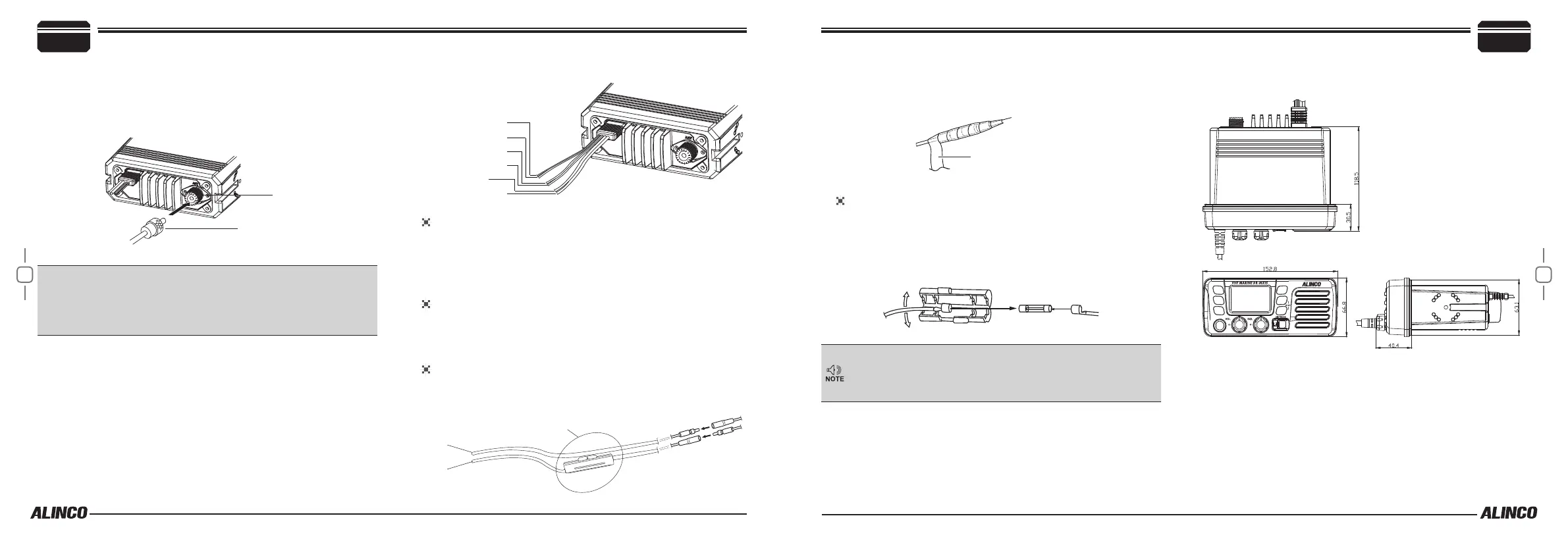
Antenna Connection
Please connect an antenna before transmitting. Use appropriate VHF
marine-radio antenna and connect to the ANT (antenna) port. The coax
cable must be 50Ω. Please consult with your dealer for antenna and nec-
essary hardware.
PL-259 connector
Antenna
port
IMPORTANT: Transmitting without rst connecting an antenna or other
matched load may damage the transceiver. Always connect the anten-
na to the transceiver before transmitting.
All xed stations should be equipped with a lightning arrester to reduce
the risk of re, electric shock, and damages.
■
Connections
Blue:
: GND (–)
NMEA IN (+)
Speaker (+)
Speaker (–)
NMEA IN (–)
GPS Receiver Lead
Connect the yellow lead “NMEA IN(+)” and green lead “NMEA IN(-)” to
a GPS receiver for position indication.
• An NMEA0183 ver.2.0 or 3.01 (sentence formatters RMC, GNS,
GLL) compatible GPS receiver is required.
External Speaker Lead
Connect the blue lead “Speaker(+)” and gray lead “Speaker(-)” to an
external speaker. An external speaker with output 5W, impedance 4Ω
is recommended to connect.
DC Power Connector
Connect the supplied DC power cable from this connector to an exter-
nal 13.8V DC power source. NEVER connect to 24VDC direct.
Black: GND(–)
Red: DC13.8V(+)
FUSE
2
Initial Installation
After connecting the DC power cable, GPS receiver lead and external
speaker lead, cover the connector and leads with an adhesive tape as
below, to prevent water seeping into the transceiver.
Self vulcanizing tape
Fuse Replacement
If a fuse blows, remove the DC cable, x the cause of trouble and re-
place it with a spare. Consult your radio / ship dealer If it continues to
blow.
• Please power off before replacing the fuse, the required fuse is
DC10A/250V.
Avoid using the high-power marine radio when the ship battery is
not suciently charged. Transmitting high power consumes cur-
rent and risks battery discharge.Transmitting high-power drains
nearly 5.5A.
■
Dimensions
Unit: mm