KINTEX UltraScale+ FPGA Board AXKU040 User Manual
Part 15: LED Light
There are Six red LEDs on the AXKU040 FPGA development board, one
of which is the power indicator (PWR), one is DONE indicator,four are users
LED lights. When the AXKU040 FPGA board is powered on, the power
indicator will light up; when the AXKU040 FPGA is configured, the
configuration LED will light up; 4 user LEDs are connected to the IO of the
FPGA BANK65, the user can control the lighting and extinction through the
program. When the IO voltage connected to the user LED is configured low
level, the user LED lights up. When the connected IO voltage is configured as
high level, the user LED will be extinguished. Because the level of BANK65 is
1.8V, here we have added a three-stage tube to drive the LED to light up.
DONE light to judge whether FPGA startup is normal
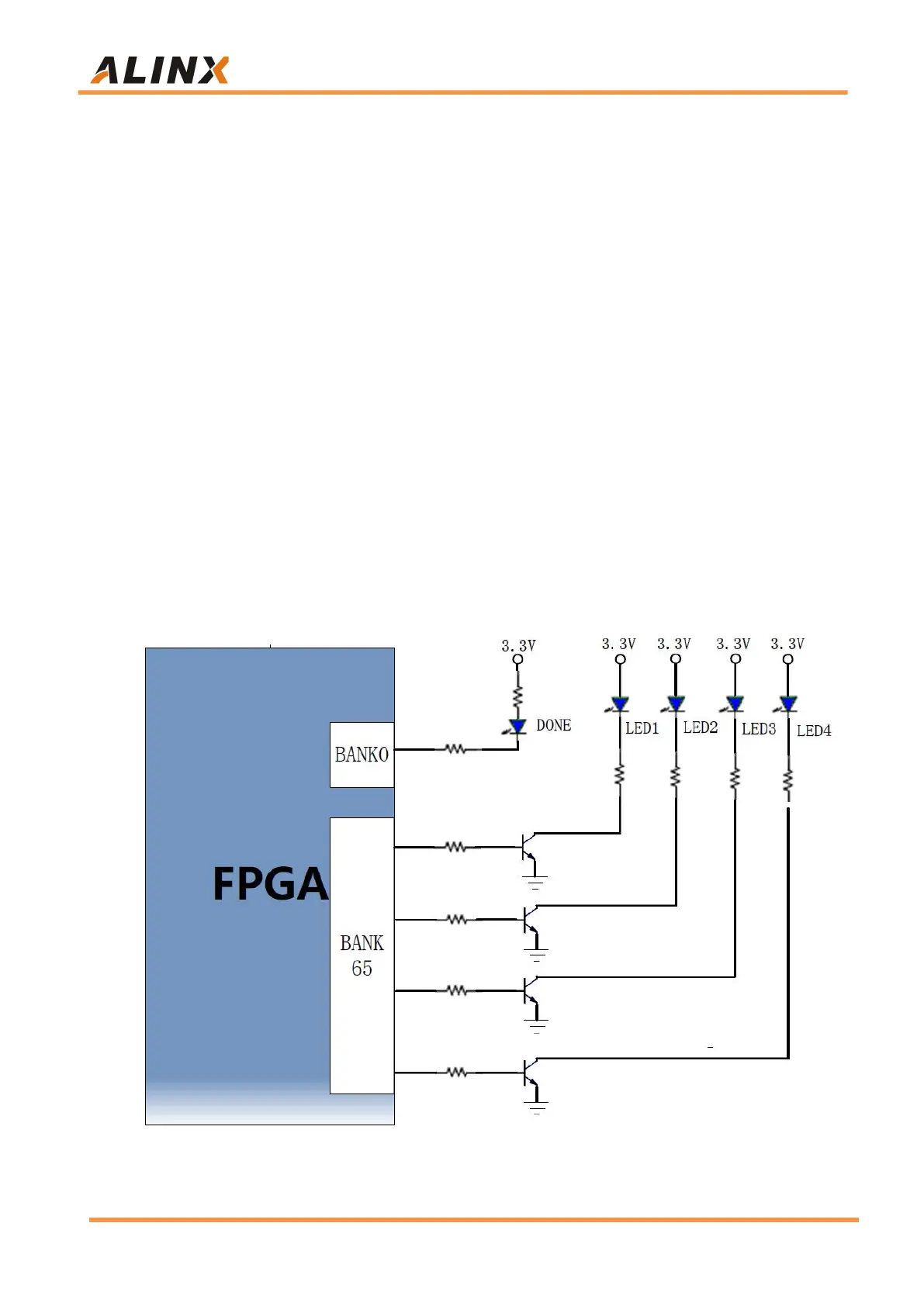
The LEDs hardware connection is shown in Figure 15-1.
Figure 15-1: The LED lights hardware connection diagram