KINTEX UltraScale+ FPGA Board AXKU040 User Manual
Part 7: SFP+ Optical fiber interface
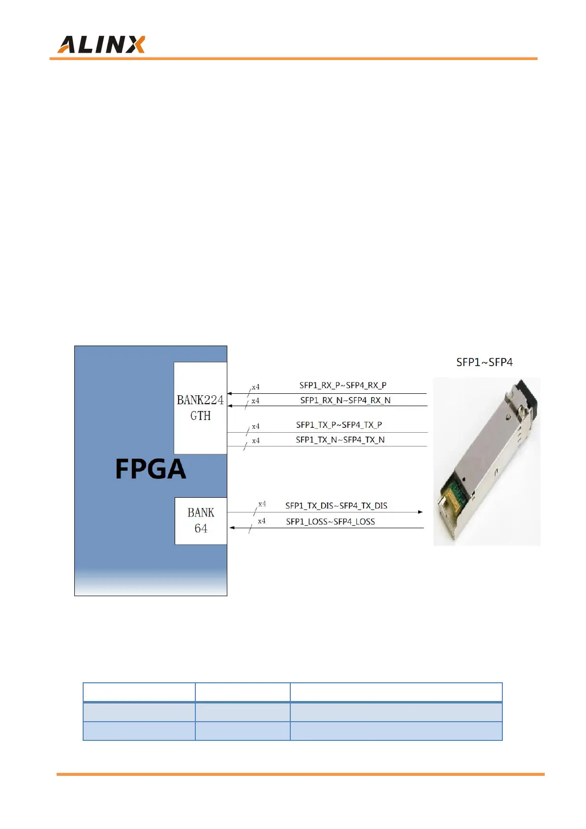
The AXKU040 FPGA development board has a four SFP interface. The
Users can buy SFP optical modules (1.25G, 2.5G, 10G optical modules on the
market) and insert them into these 4 optical fiber interfaces for optical fiber data
communication. The 4 optical fiber interfaces are respectively connected with 4
RX/TX of FPGA BANK24 GTH transceiver. Both the TX signal and the RX
signal are connected to the FPGA and the optical module through a DC
blocking capacitor in a differential signal mode, and the data rate of each TX
transmission and RX reception is as high as 12.5Gb/s. The reference clock of
the GXH transceiver of BANK224 is provided by a differential crystal oscillator
125M.
Figure 7-1: SFP Fiber Design Diagram
The 1
st
fiber interface FPGA pin assignment is as follows:
SFP1 Data Transmission (Positive)
SFP1 Data Transmission (Negative)