SSI Servo Module 13
Publication
1756-IN595A-EN-P - March 2004
Assembling the Removable Terminal Block and the Housing
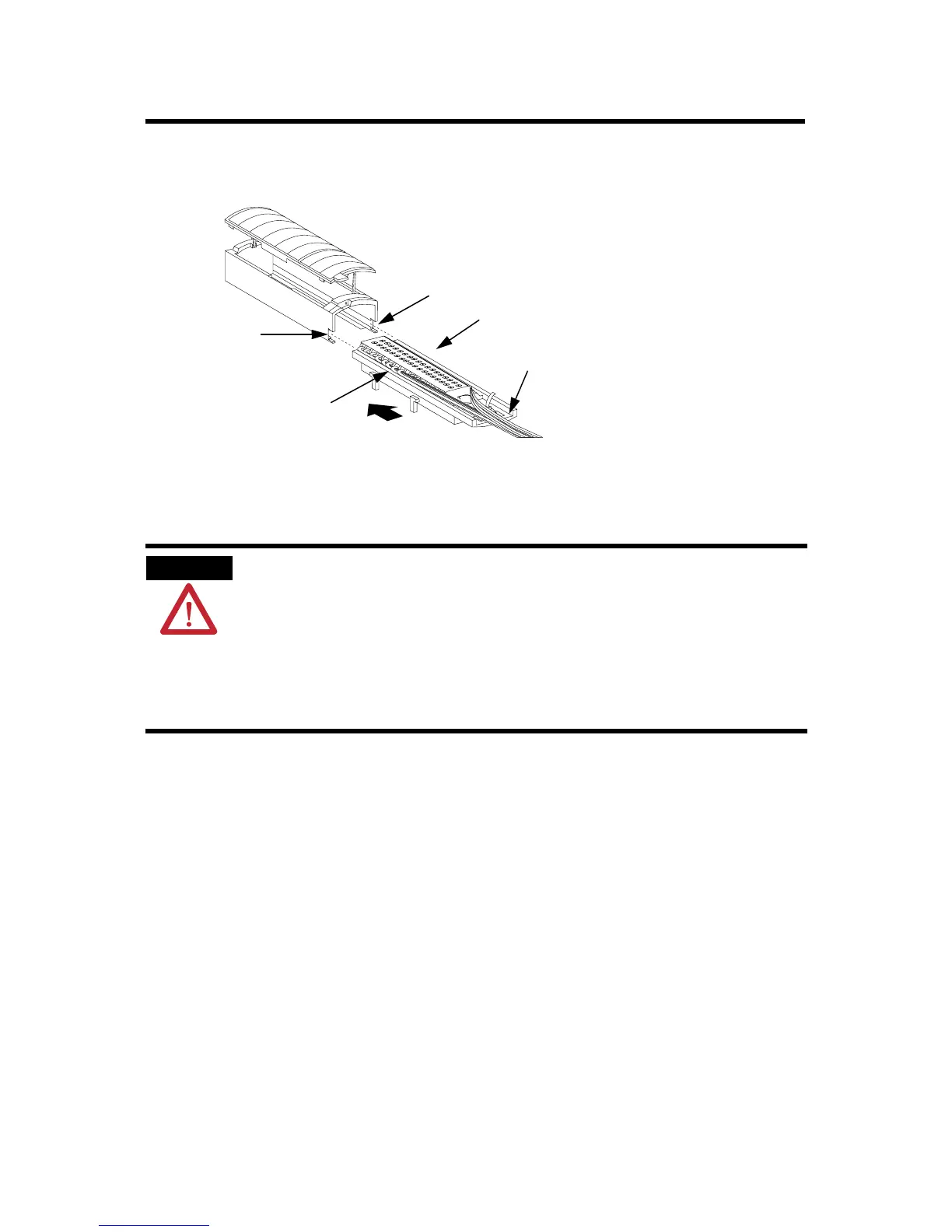
Figure 11 RTB and Housing
Installing the Removable Terminal Block onto the Module
Before installing the RTB, make certain:
• field-side wiring of the RTB has been completed.
• the RTB housing is snapped in place on the RTB.
• the RTB housing is closed.
• the locking tab at the top of the module is unlocked.
WARNING
When you connect or disconnect the Removable Terminal Block
(RTB) with field side power applied, an electrical arc can occur.
This could cause an explosion in hazardous location
installations.
Be sure that power is removed or the area is nonhazardous
before proceeding.
20858–M
Groove
Groove
Side edge of the RTB
Side edge of the RTB
Strain relief area
1. Align the grooves at the bottom of the housing with the side edges of the RTB.
2. Slide the RTB into the housing until it snaps into place.
Spare Allen-Bradley Parts

 Loading...


