6 SSI Servo Module
Publication
1756-IN595A-EN-P - March 2004
Installing the Module
You can install or remove the module while chassis power is applied.
Repeated electrical arcing causes excessive wear to contacts on both the
module and its mating connector. Worn contacts may create electrical
resistance that can affect module operation.
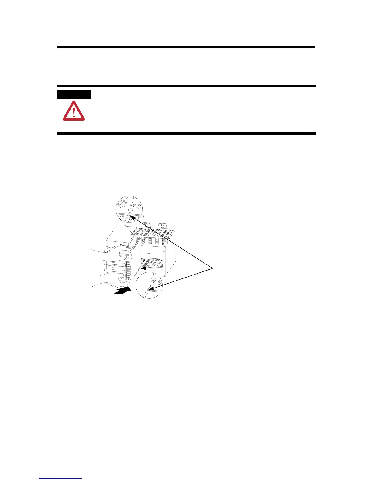
1. Align the circuit board with the top and bottom chassis guides.
Figure 1 Circuit Board Alignment
WARNING
When you insert or remove the module while backplane power is
on, an electrical arc can occur. This could cause an explosion in
hazardous location installations. Be sure that power is removed
or the area is nonhazardous before proceeding.
20861-M
Printed Circuit Board

 Loading...


