SSI Servo Module 19
Publication
1756-IN595A-EN-P - March 2004
Removing the Removable Terminal Block from the Module
If you must remove the module, you have to remove the RTB first.
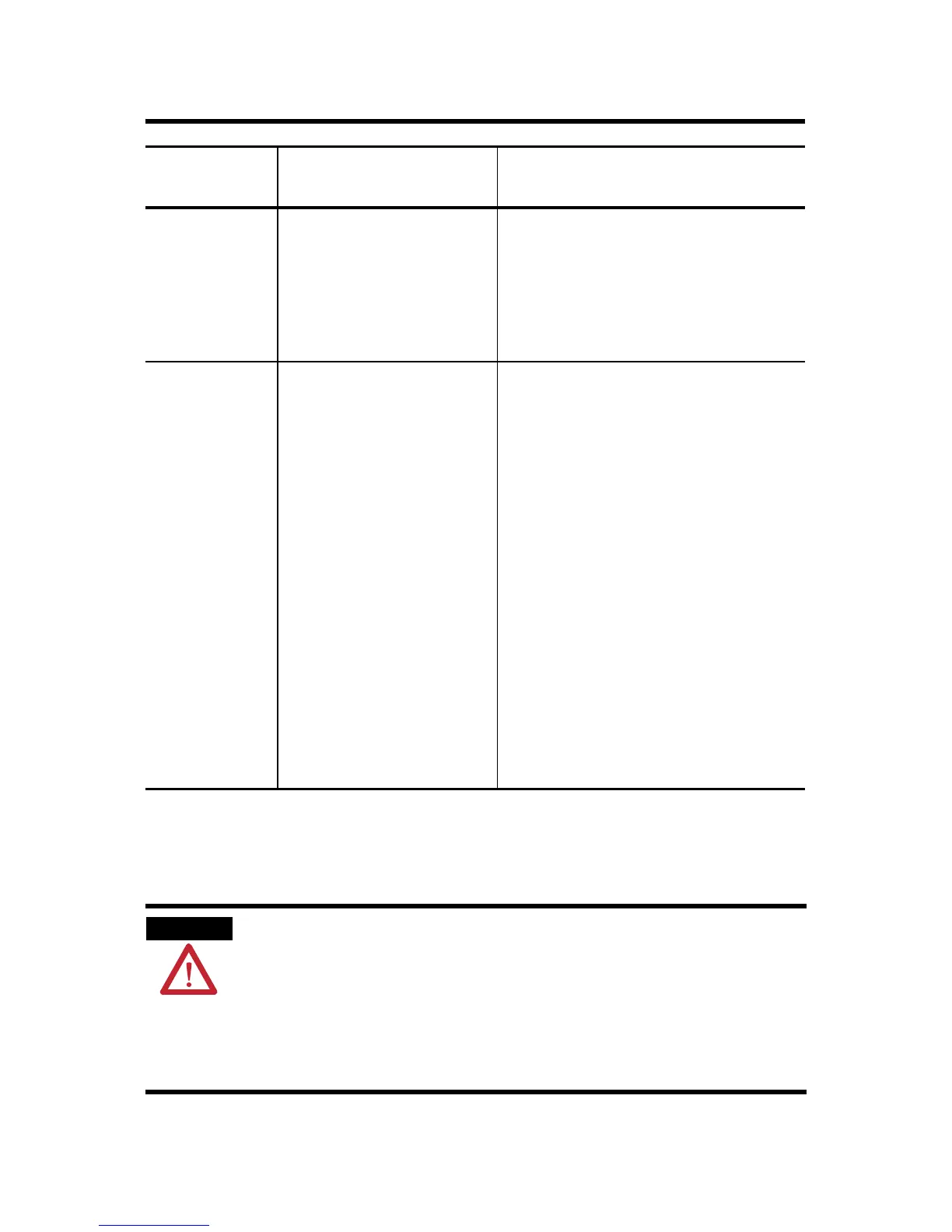
Flashing red
light
The axis drive output is in
the shutdown state.
• Check for faults that may have
generated this state.
• Execute the Motion Axis
Shutdown Reset instruction.
• Resume normal operation.
Steady red light The axis drive is faulted. • Check the drive status.
• Clear the Drive Fault condition
at the drive.
• Clear the servo fault condition
using the Motion Axis Fault
Reset instruction.
• Resume normal operation.
• Check the configuration for the
Drive Fault.
• If configured to be normally
open and there is no voltage,
this is the normal condition.
• If configured to be normally
closed and 24V dc is applied,
this is the normal condition.
WARNING
When you connect or disconnect the Removable Terminal Block
(RTB) with field side power applied; an electrical arc can occur.
This could cause an explosion in hazardous location
installations.
Be sure that power is removed or the area is nonhazardous
before proceeding.
If the DRIVE
LED displays:
The module status is: Take this action:
Spare Allen-Bradley Parts

 Loading...


