SSI Servo Module 7
Publication
1756-IN595A-EN-P - March 2004
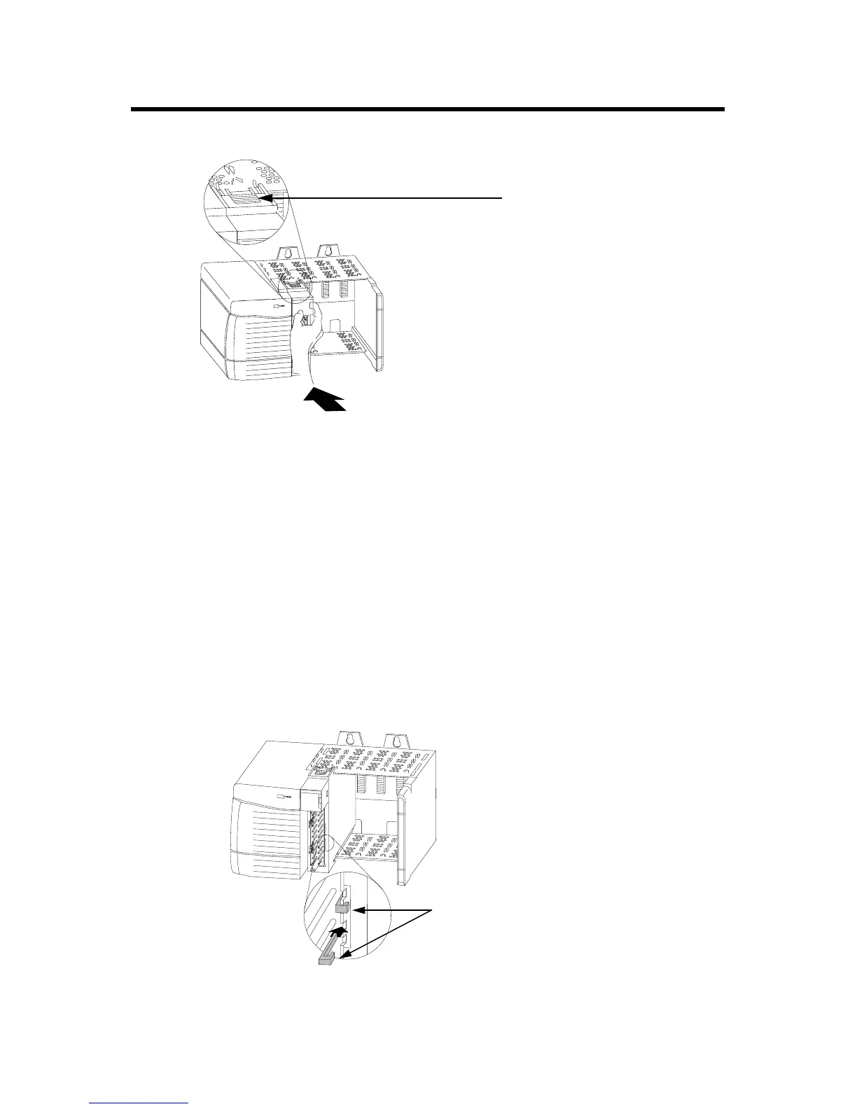
2. Slide the module into the chassis until module tabs ‘click’.
Figure 2 Module Locking Tabs
Keying the Module and Removable Terminal Block/Interface
Module
Use the wedge-shaped keying tabs and U-shaped keying bands to prevent
connecting the wrong wires to your module.
Key positions on the module that correspond to unkeyed positions on the
RTB. For example, if you key the first position on the module, leave the first
position on the RTB unkeyed.
1. To key the module, insert the U-shaped band, as shown.
Figure 3 Keying Band
20862-M
Locking Tab
20850–M
U-shaped
bands
Spare Allen-Bradley Parts

 Loading...


