14 SSI Servo Module
Publication
1756-IN595A-EN-P - March 2004
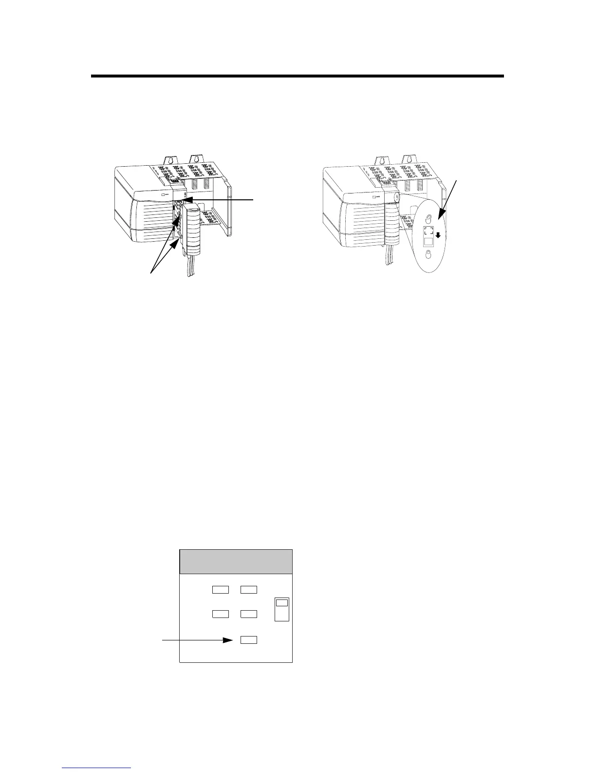
Figure 12 Seating the RTB
Checking the LED Indicators
The module uses a single bi-colored LED to indicate module OK status and
bi-colored LED indicators to show individual feedback (FDBK) and drive
(DRIVE) status for both axes.
During power up, the module completes an indicator test. The OK indicator
turns red for 1 second and then turns to flashing green if the module passes
all its self tests.
Module Status Using the OK Indicator
Figure 13 OK Indicator LED
20853–M 20854–M
Module
guide
RTB guides
Locking tab
1. Align the module and RTB guides to
make sure the module will seat properly.
2. Press quickly and evenly to seat the RTB
until the latches snap into place.
3. To lock the RTB on the module,
slide the locking tab down.
OK indicator
CH0 CH1
FDBK
DRIVE
OK
2 AXIS SERVO / SSI
FDBK
DRIVE

 Loading...


