EasyManuals Logo

Allen-Bradley 1756-M02AS Installation Instructions

Allen-Bradley 1756-M02AS
26 pages
To Next Page IconTo Next Page
To Previous Page IconTo Previous Page
Page #9 background imageLoading...
Page #9 background image
SSI Servo Module 9
Publication
1756-IN595A-EN-P - March 2004
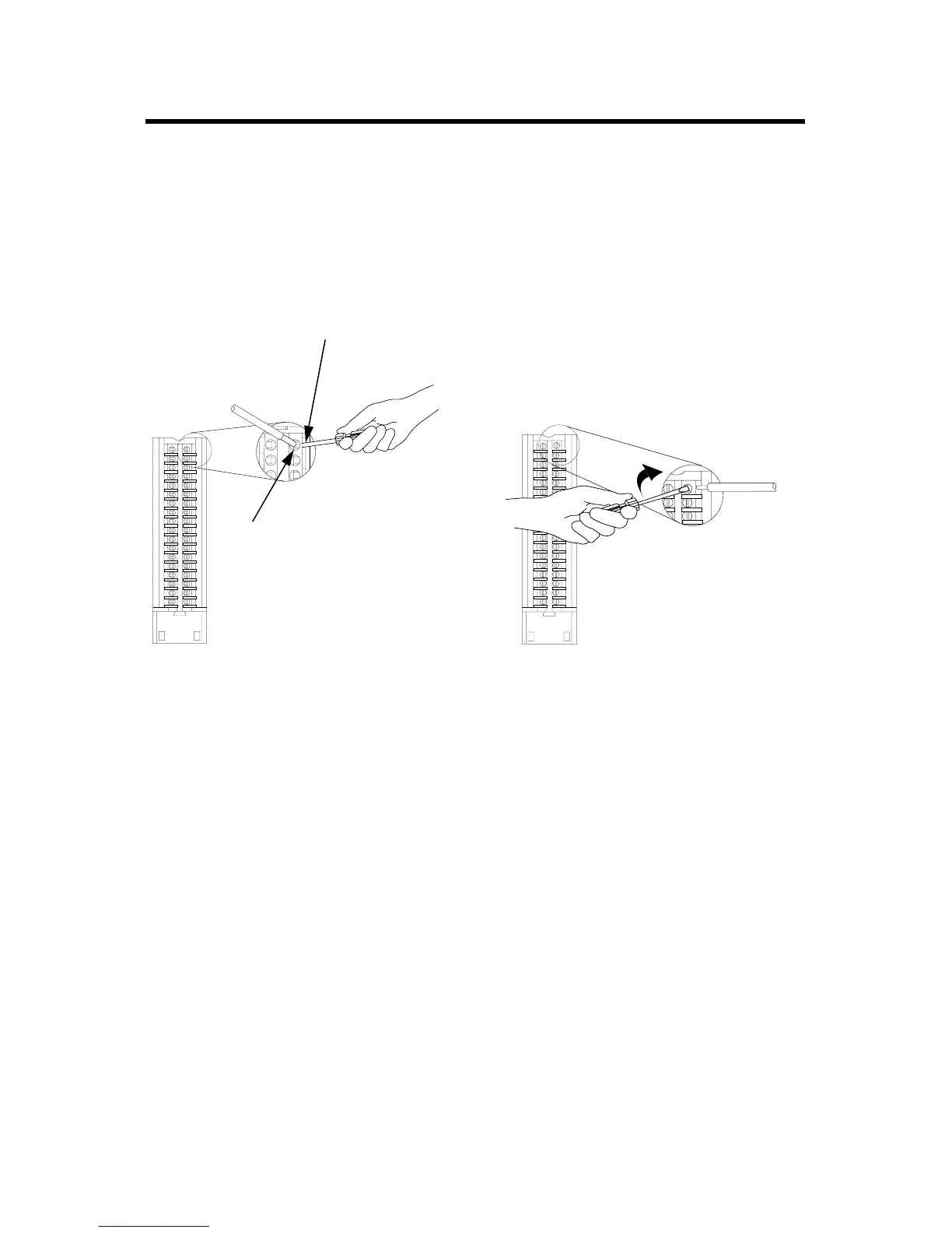
Connect the wires as shown below.
Figure 5 Connecting to Spring Clamp and Cage Clamp RTBs
Spring Clamp RTB Cage Clamp RTB
20860-M
20859-M
1. Strip 7/16 inch (11mm) maximum
length of wire.
2. Insert the screwdriver into the
inner hole of the RTB.
3. Insert the wire into the
open terminal and
remove the screwdriver.
1. Strip 3/8 inch (9.5mm) maximum
length of wire.
2. Insert the wire into the open terminal.
3. Turn the screw clockwise to close the
terminal on the wire.
Spare Allen-Bradley Parts

Other manuals for Allen-Bradley 1756-M02AS

Questions and Answers:

Question and Answer IconNeed help?

Do you have a question about the Allen-Bradley 1756-M02AS and is the answer not in the manual?

Allen-Bradley 1756-M02AS Specifications

General IconGeneral
BrandAllen-Bradley
Model1756-M02AS
CategoryControl Unit
LanguageEnglish

Related product manuals