Installation
Chapter 3
33
1. Connect the power cable between the recorder and a grounded 115V
AC outlet.
NOTE: If the recorder has been converted for 230V AC operation, use a
230V AC outlet.
2. Connect a Digital Cassette Recorder Cable (cat. no. 1772-TH)
between the recorder and the industrial terminal system. Connect the
end labeled CASSETTE to the connector labeled A-B
CONTROLLER EQUIPMENT on the recorder. Connect the other
end to the connector labeled CHANNEL C on the industrial terminal
system.
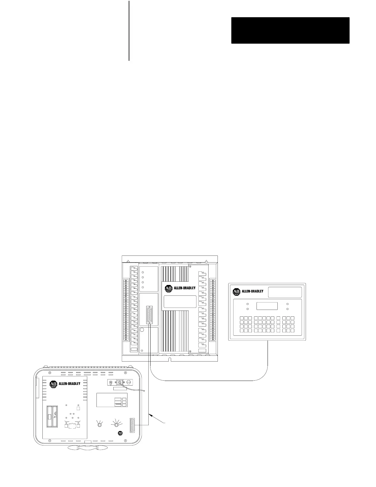
Use the following procedure to connect the recorder to PLC-4 Microtrol
programmable controllers (Figure 3.3).
1. Connect the power cable between the recorder and a grounded 115V
AC outlet.
NOTE: If the recorder has been converted for 230V AC operation, use a
230V AC outlet.
Figure 3.3
Connection
to a PLC4 Microtrol Programmable Controller
POWER
Digital Cassette
Recorder Cable
(Cat. No. 1772TH)
PLC4
Microtrol
PLC4
Microtrol
11296
Connection to PLC4 Microtrol
Programmable Controllers
Artisan Technology Group - Quality Instrumentation ... Guaranteed | (888) 88-SOURCE | www.artisantg.com
 Loading...