Chapter
2
21
Recorder Hardware
This chapter describes the various switches, indicators, connectors, and
labels associated with the Allen–Bradley data cartridge recorder.
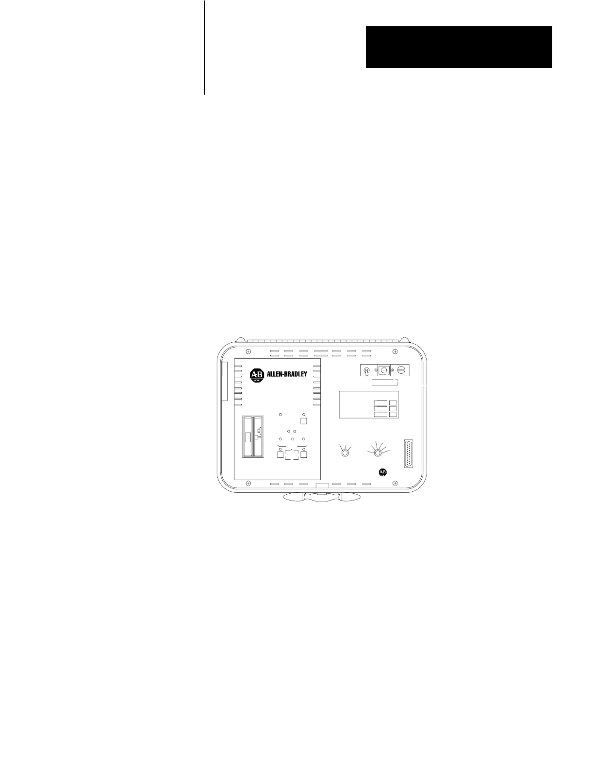
There are six switches on the recorder. Figure 2.1 shows the position of
the switches on the recorder front panel. Table 2.A lists switch functions.
Figure 2.1
Data
Cartridge Recorder Front Panel
POWER
10846I
There are ten LED indicators on the recorder. Figure 2.1 shows the
position of these indicators on the recorder front panel. Table 2.B lists
indicator functions.
The data cartridge recorder interfaces with Allen–Bradley products
through a 25–pin RS–232–C connector labeled A–B CONTROLLER
EQUIPMENT. This connector attaches to one end of a Cassette Recorder
Interconnect Cable (cat. no. 1774– TD), or a Digital Cassette Recorder
Cable (cat. no. 1772–TH).
The other end of the cable attaches to the Allen–Bradley product used
with the recorder. Installation with specific products is described in
chapter 3.
General Description
Switches
Indictors
Data Interface
Artisan Technology Group - Quality Instrumentation ... Guaranteed | (888) 88-SOURCE | www.artisantg.com
 Loading...