EasyManuals Logo

Allen-Bradley E300 Quick Start Instructions

Allen-Bradley E300
44 pages
To Next Page IconTo Next Page
To Previous Page IconTo Previous Page
Page #11 background imageLoading...
Page #11 background image
Rockwell Automation Publication 193-QR004B-EN-P - January 2017 11
Chapter 1
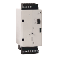
3. Install the I/O connectors.
Two of the I/O connectors attach to the bottom of the control modules. The third connector attaches to the top
of th
e control module
You have completed the assembly of the E300 Overload Relay.
Sensing Module Latch
Power / PTC
Terminals
Expansion Bus Connector
Relay / Ground Fault
Terminals
Power / Input / PTC
Ter mi na ls
Relay/Ground Fault Terminals
Power / Input / PTC
Ter mi na ls
Expansion Bus Connector
Sensing Module Latch

Other manuals for Allen-Bradley E300

Questions and Answers:

Question and Answer IconNeed help?

Do you have a question about the Allen-Bradley E300 and is the answer not in the manual?

Allen-Bradley E300 Specifications

General IconGeneral
TypeElectronic Overload Relay
MountingDIN Rail or Panel Mount
Protection ClassIP20
Voltage Range24…690 V AC/DC
Communication OptionsEtherNet/IP, DeviceNet
ProtectionOverload, phase loss, ground fault
Operating Temperature-20°C to 60°C

Related product manuals