Timer and Counter Instructions
Chapter 5
512
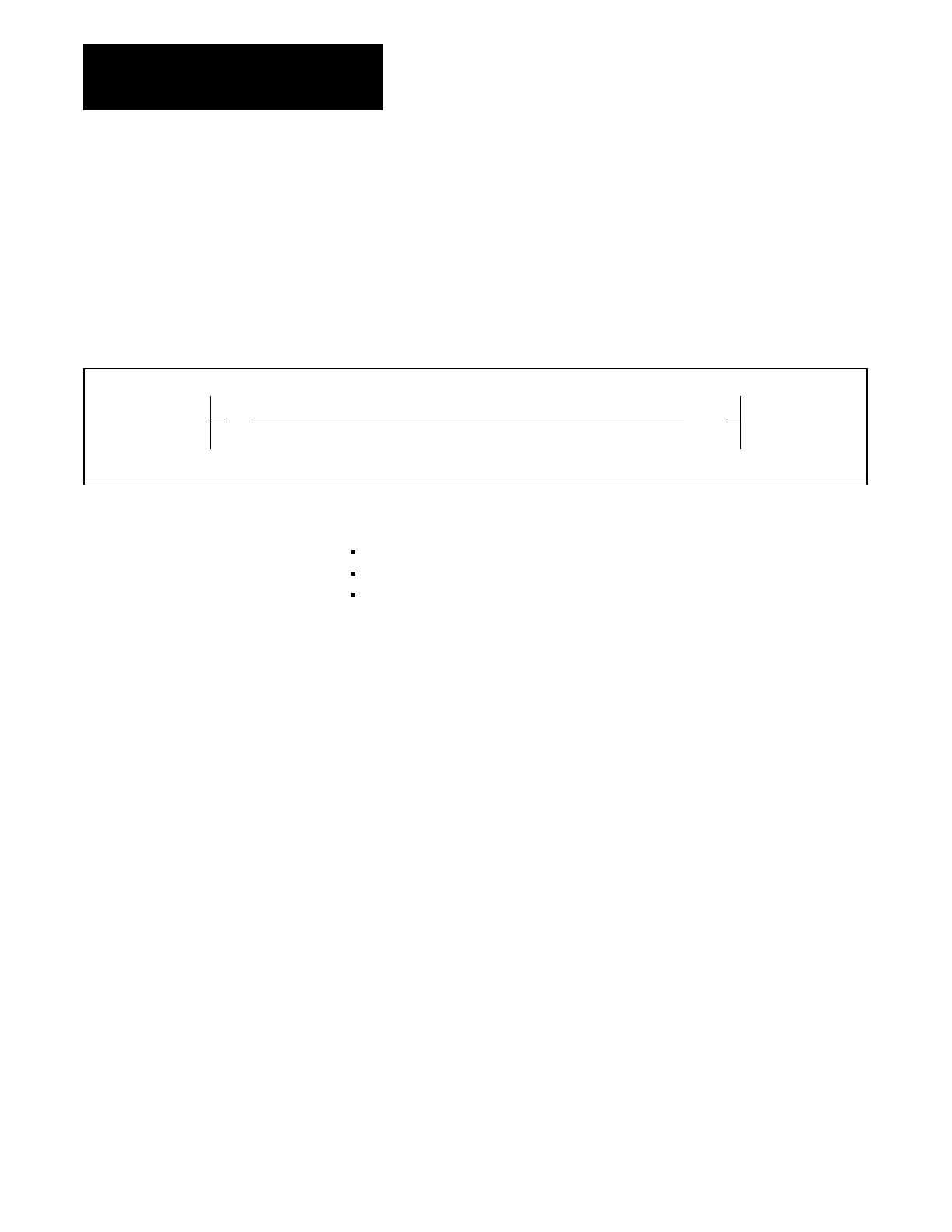
The Down-Counter (CTD) instruction subtracts one from its Accumulated
Value for each false-to-true transition of its rung conditions (Figure 5.9).
Because only the false-to-true transition causes a count to be made, rung
conditions must go from true to false and back to true before the next count
is registered.
Figure 5.9
DownCounter
Instruction
||
02
(
CTD )
113 054
PR 100
AC 150
The CTD accumulated value is retained when:
Mode Select Switch is changed to the PROGRAM position
Rung conditions go false
Power outage occurs provided memory backup power is maintained for
CMOS RAM memory
Each time the CTD rung goes true, bit 16, the enabled bit, is set on. When
the Accumulated Value is greater than or equal to the Preset Value, bit 15 is
set on. When the Accumulated Value goes below 000, bit 14 is set on to
indicate an underflow condition and the CTD continues down-counting
from 999.
Normally, the Down-Counter instruction is paired with the Up-Counter
instruction to form an Up/Down Counter, using the same word address,
AC value and PR value (Figure 5.10).
5.2.3
DownCounter Instruction
Artisan Technology Group - Quality Instrumentation ... Guaranteed | (888) 88-SOURCE | www.artisantg.com
 Loading...


