Output Override and I/O Update Instructions
Chapter 7
711
Fault zones can be programmed around certain parts of the program or the
entire program using fault status bits and MCR or ZCL zones. The fault
status bits used for remote fault zone programming are located in data table
words 125
8
and 126
8
(Table 7.B).
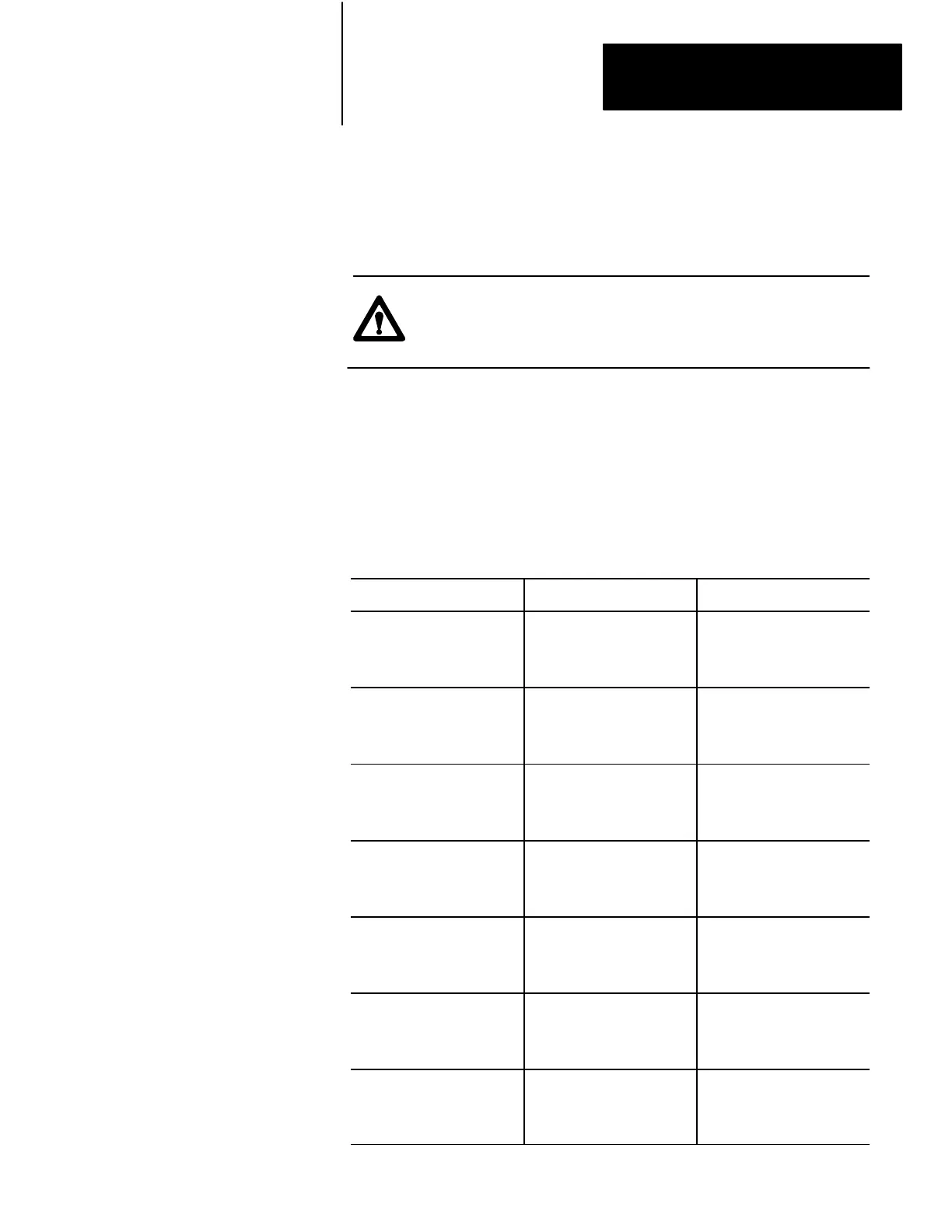
CAUTION: Input modules cannot be located in rack 2, module
groups 5 and 6 if words 125 and 126 are used for fault status
bits.
A group of four fault status bits corresponds to a single I/O rack
(Table 7.B). For example, bits 125/07
8
–125/04
8
correspond to rack 1, and
bits 125/03
8
–125/00
8
correspond to rack 2. Although bits 126/13
8
–126/10
8
are not used as fault status bits, they cannot be used for storage.
Table 7.B
Fault
Status Bits
I/O Rack Module Groups Fault Status Bit
1 0, 1
2, 3
4, 5
6, 7
125/07
125/06
125/05
125/04
2 0, 1
2, 3
4, 5
6, 7
125/03
125/02
125/01
125/00
3 0, 1
2, 3
4, 5
6, 7
125/17
125/16
125/15
125/14
4 0, 1
2, 3
4, 5
6, 7
125/13
125/12
125/11
125/10
5 0, 1
2, 3
4, 5
6, 7
126/07
126/06
126/05
126/04
6 0, 1
2, 3
4, 5
6, 7
126/03
126/02
126/01
126/00
7 0, 1
2, 3
4, 5
6, 7
126/17
126/16
126/15
126/14
Artisan Technology Group - Quality Instrumentation ... Guaranteed | (888) 88-SOURCE | www.artisantg.com
 Loading...


