Hardware Considerations
Chapter 2
27
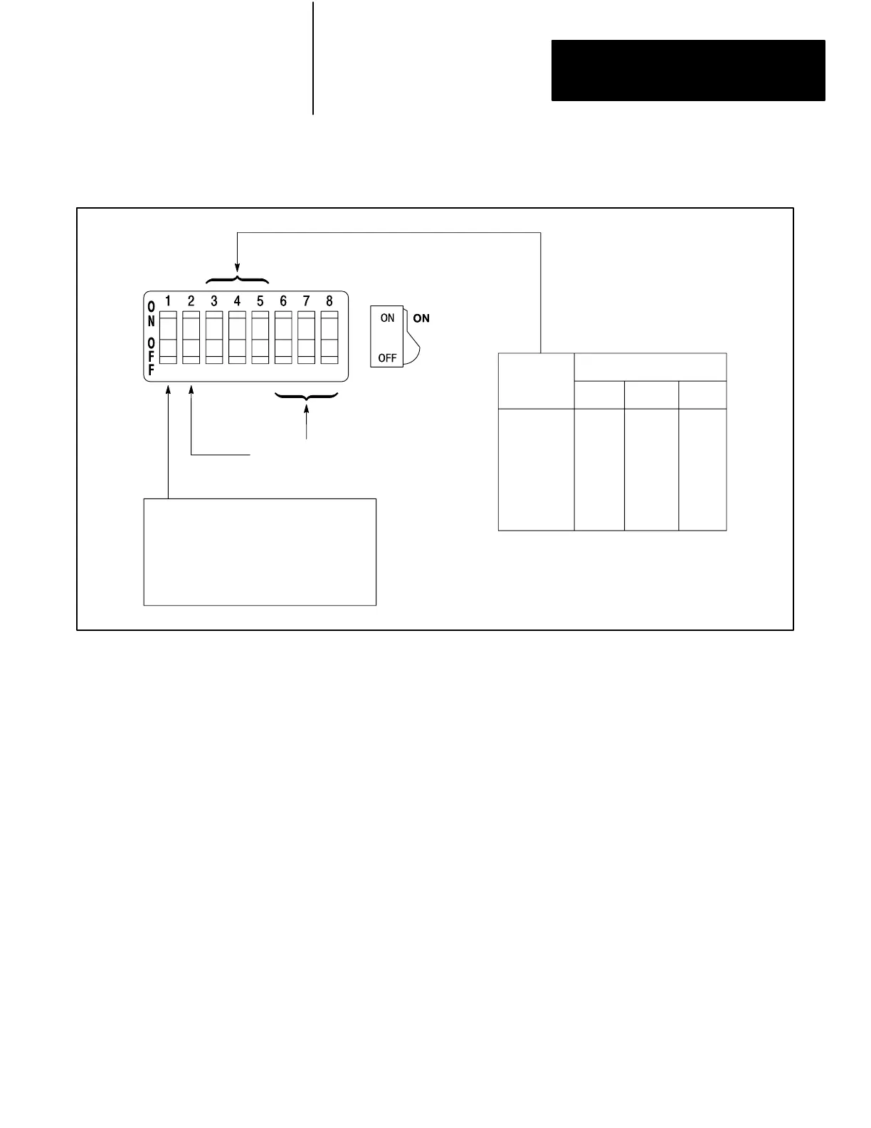
Figure 2.3
1771
I/O Chassis Backplane Switch Settings for Local I/O Systems
Local
Rack
Numbers
Switch
354
1
2
3
4
5
6
7
On
On
On
On
Off
Off
Off
On
Off
On
Off
On
Off
On
On
On
Off
Off
On
On
Off
On:
Outputs remain in last state
when fault is detected.
Off:
Outputs deenergized when
fault is detected.
No significance -
should be set to OFF
The 1770-T3 and 1784-T50 industrial terminals are the primary
programming terminals for the PLC-2/30 programmable controller. They
are used to load, edit, monitor and troubleshoot the user’s program in the
PLC-2/30 memory.
For detailed information about the 1770-T3 Industrial Terminal, refer to
the Industrial Terminal System User’s Manual, publication no. 1770-6.5.3.
For detailed information about the 1784-T50 Industrial Terminal, refer to
the Industrial Terminal T50 User’s Manual, publication no. 1784-6.5.1.
A local system has the processor and each I/O chassis within 3-6 cable feet
of each other. Up to 7 local I/O racks may be assigned.
For proper transmission of data between the PLC-2/30 processor and
local bulletin 1771 I/O modules, the I/O chassis must contain a local I/O
Adapter Module (Cat. No. 1771-AL). The local adapter module must be
installed in each I/O chassis used with the processor. Diagnostic indicators
2.7
Industrial Terminal
2.8
Local System Structure
Artisan Technology Group - Quality Instrumentation ... Guaranteed | (888) 88-SOURCE | www.artisantg.com
 Loading...


