Bit Shifts
Chapter 14
1411
Instruction overview:
Output instruction
3 words of users program required
Key sequence: [SHIFT REG] 17
To program a Reset Shift Bit instruction press [SHIFT REG] 17. A display
represented by Figure 14.10 will appear.
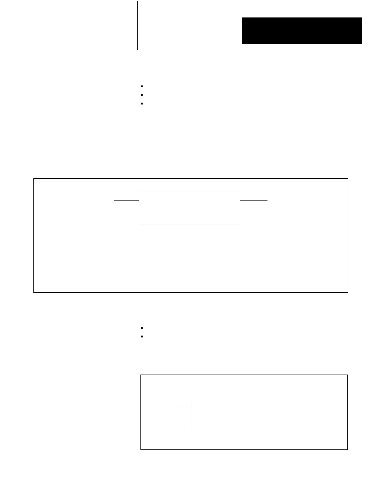
Figure 14.10
RESET
SHIFT BIT Format
RESET SHIFT BIT
FILE: 110
BIT NO.: 001
Numbers
shown are default values. Bold numbers must be replaced by userentered values. The number of default address digits
initially displayed 3, 4, or 5 will depend on the size of the data table. Initially displayed default values are governed by the I/O rack
configuration.
FILE :
Starting address of the file (file of bit shift instruction).
BIT NUMBER
:
Decimal number of the bit to be set (1999).
Figure 14.11 shows the format of Figure 14.10 for the following condition
of the bit shift register of Figure 14.1.
File – The file starts at word 400
8
.
Bit No. – Turn bit number 67 in shift register (Figure 14.1) to off (0).
Figure 14.11
RESET
SHIFT BIT Example Rung
RESET SHIFT BIT
FILE: 400
BIT NO.: 067
14.6.1
Programming Reset Shift Bit
Instruction
Artisan Technology Group - Quality Instrumentation ... Guaranteed | (888) 88-SOURCE | www.artisantg.com
 Loading...


