Addressing
Appendix A
A2
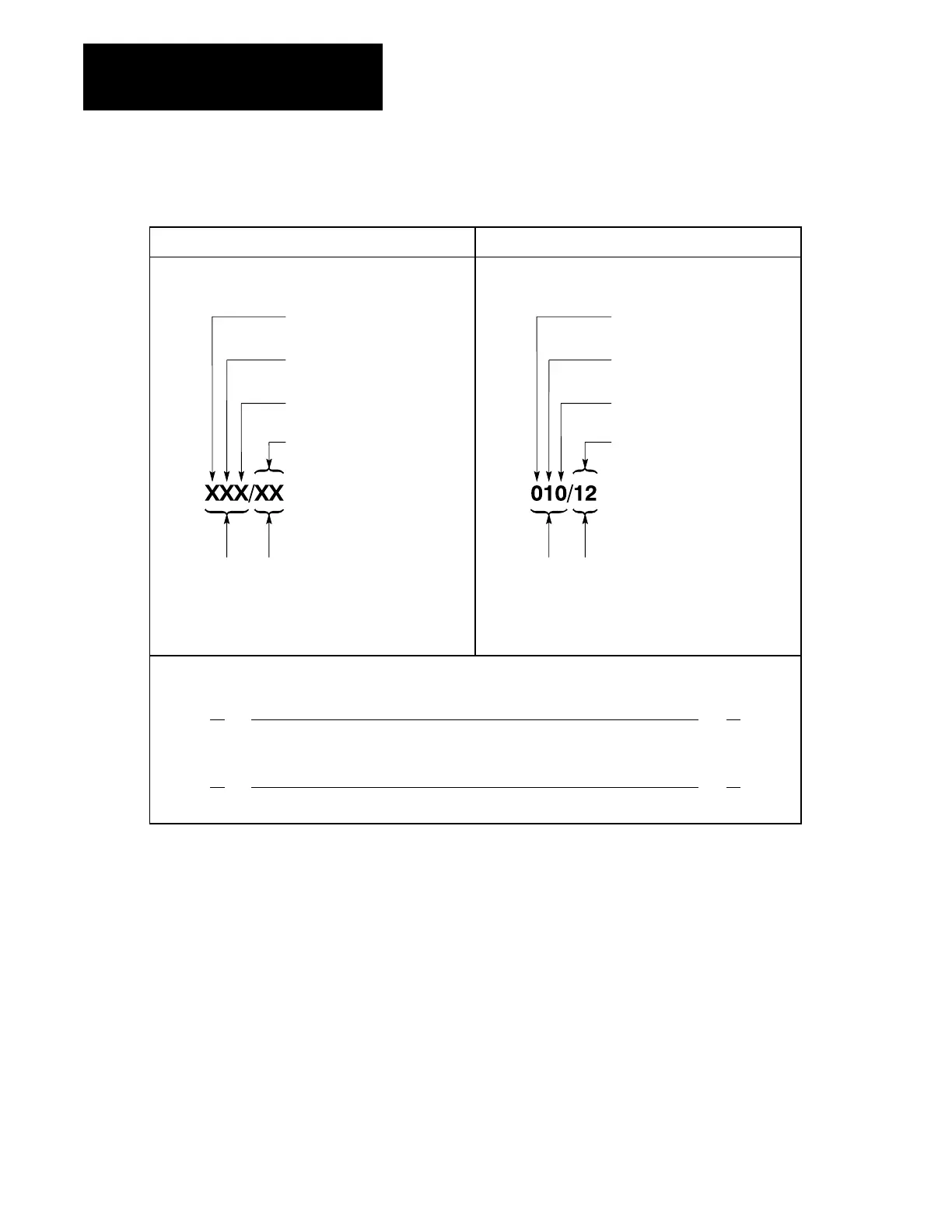
Figure A.1
Hardware/Data
T
able Addressing Relationships
Concept Example
Hardware Terminology Hardware Terminology
Input
(1) or Output (0)
Rack No. (17)
I/O Group No.
(07)
T
erminal No.
(0007, 1017)
Word
Address
Bit
Address
Data Table Terminology Instruction Address
Output: 0
Rack No.: 1
Word
Address
Bit
Address
I/O Group No.: 0
T
erminal No.: 12
Program Rung
||
XX
()
XX
XXX XXX
||
11
()
112 010
12
Concept
Example
The PLC-2 family processors (at the appropriate series and revision
level) can address module groups in various addressing modes. The term
“addressing mode” refers to the method of hardware addressing within
individual I/O chassis. The selected mode(s) determines the type of module
that can be used (8-point, 16-point or 32-point). The following subsections
discuss how these modes work and how you use them. (Table A.A at the
end of this appendix lists the adapters and what modes they can address.)
A.2
Addressing
Modes
Artisan Technology Group - Quality Instrumentation ... Guaranteed | (888) 88-SOURCE | www.artisantg.com
 Loading...


