Addressing
Appendix A
A15
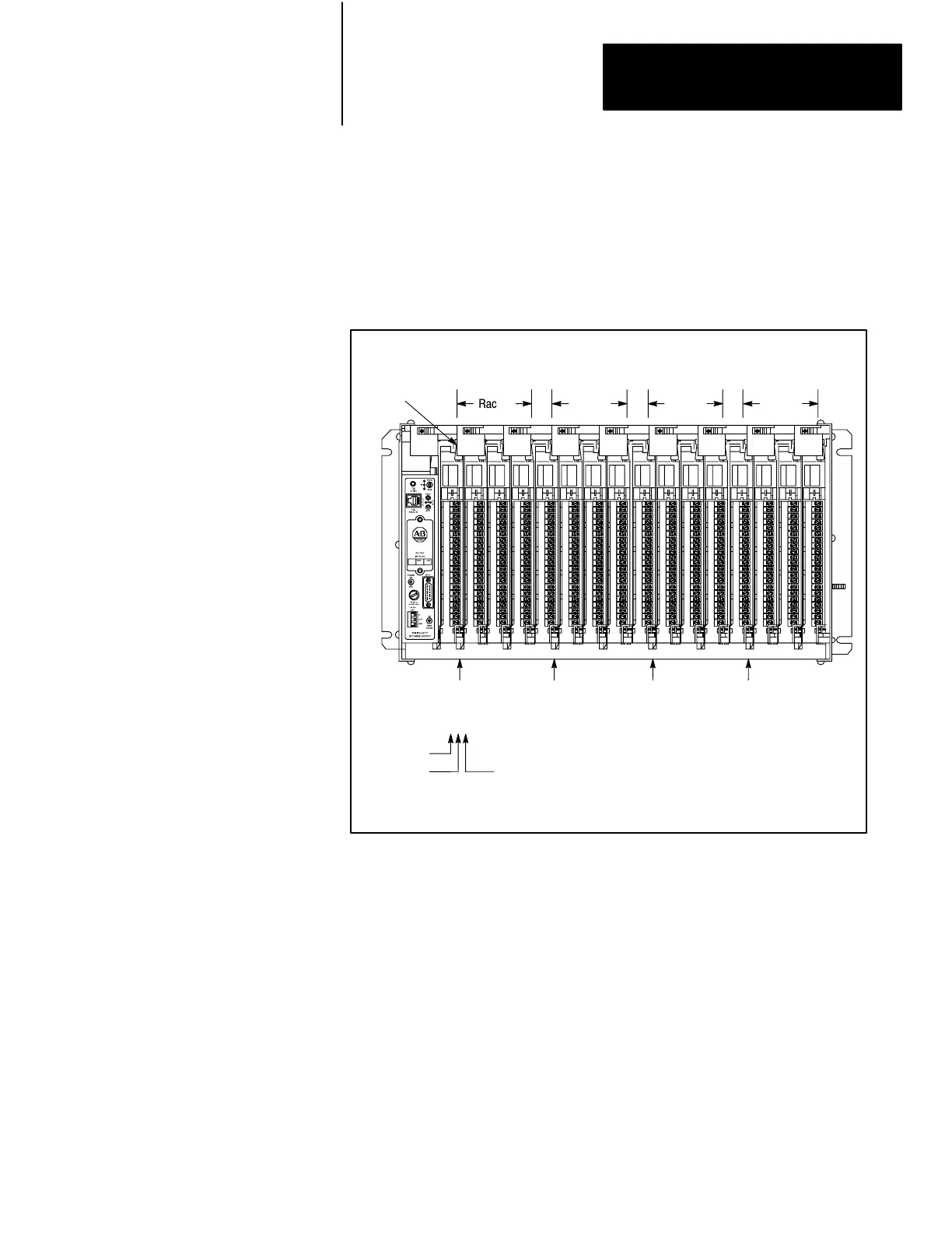
Figure A.11 illustrates addressing 4 modules, each with the same I/O group
number, but in four different racks of a single I/O chassis. (This method is
explained in Figure A.11.)
Figure A.11
Group
Address of a Module in Four Different Racks
Rack 1
I/O Group No.
03 47 03 47 03 47 03 47
I/O Group 1
Address
1 1 1
I/O Group 1
Address
121
Input
Rack
I/O Group
I/O Group 1
Address
131
I/O Group 1
Address
141
Rack 2 Rack 3 Rack 4
NOTE: When addressing a one-block transfer module, it must be
addressed by the lowest group number that it occupies and at slot 0. For
example, a one-slot block transfer module in rack 1, group 2 and 3 (chassis
slot 2) would be addressed (by Rack-Group-Slot) at location 120.
NOTE: When addressing a two-slot block transfer module, it too must be
addressed by the lowest group number that it occupies and at slot 0. For
example, a two-slot block transfer module in rack 3, groups 4, 5, 6, and 7
(it occupies chassis slots 3 and 4) would be addressed (by Rack-Group-
Slot) at location 340.
Also see the appropriate block transfer module user’s manual. Block
Transfer modules must be located in the same slot pair (i.e., slots 0/1, 2/3,
Artisan Technology Group - Quality Instrumentation ... Guaranteed | (888) 88-SOURCE | www.artisantg.com
 Loading...


