EasyManuals Logo

Allen-Bradley PowerFlex 400 Quick Start Quide

Allen-Bradley PowerFlex 400
28 pages
To Next Page IconTo Next Page
To Previous Page IconTo Previous Page
Page #10 background imageLoading...
Page #10 background image
English-10 PowerFlex 400 Adjustable Frequency AC Drive Quick Start
(1)
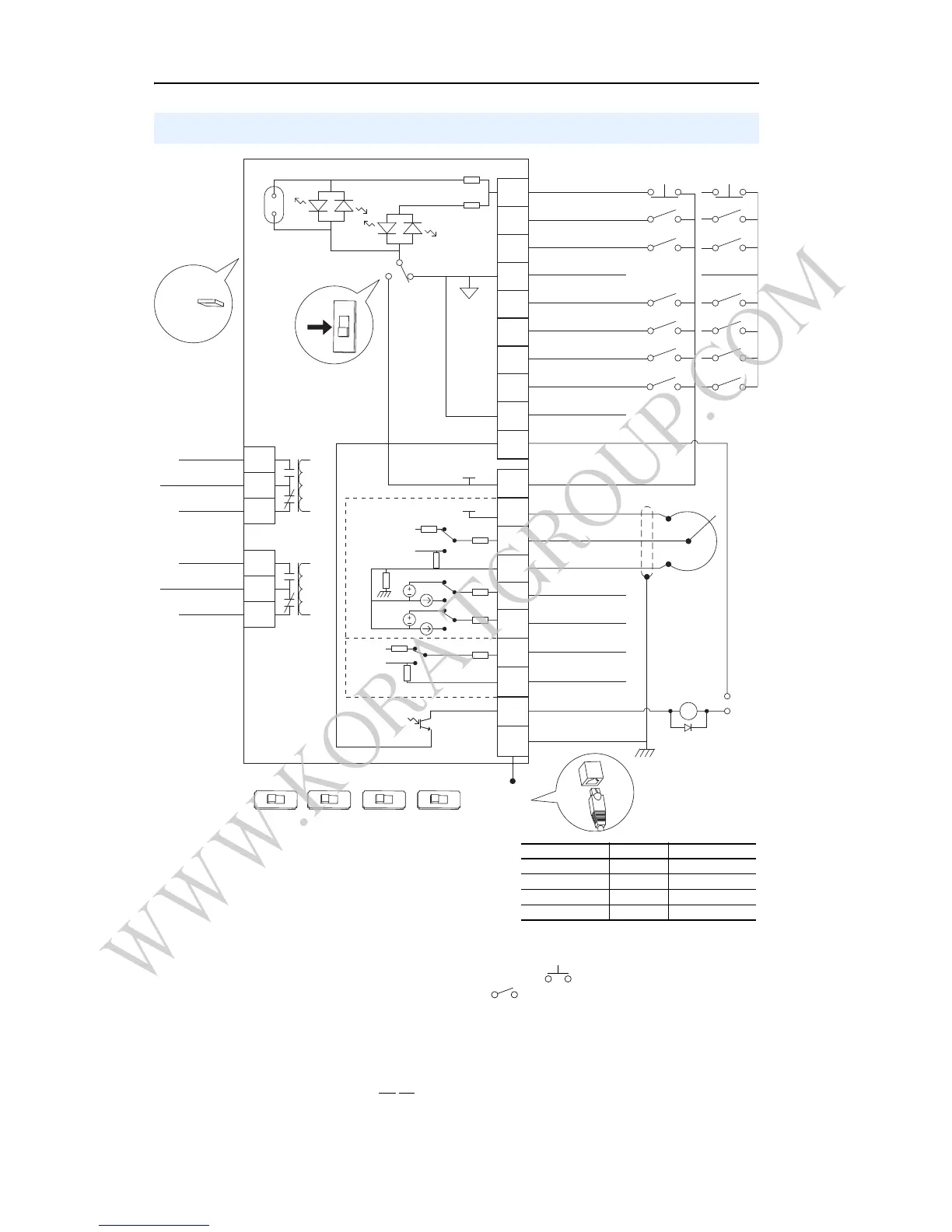
Important: I/O Terminal 01 is always a coast to stop input
except when P036 [Start Source] is set to option 1 “3-Wire” or
6 “2-W Lvl/Enbl”. In three wire control, I/O Terminal 01 is
controlled by P037 [Stop Mode]. All other stop sources are
controlled by P037 [Stop Mode].
Important: The drive is shipped with a jumper installed
between I/O Terminals 01 and 11. Remove this jumper when
using I/O Terminal 01 as a stop or enable input.
(2)
Two wire control shown. For three wire control use a momentary input on I/O Terminal 02 to command a
start. If reverse is enabled by A166, use a maintained input for I/O Terminal 03 to change direction.
(3)
When using an opto output with an inductive load such as a relay, install a recovery diode parallel to the relay as
shown, to prevent damage to the output.
(4)
When the ENBL enable jumper is removed, I/O Terminal 01 will always act as a hardware enable, causing a
coast to stop without software interpretation.
(5)
Most I/O terminals labeled “Common” are not referenced to the safety ground (PE) terminal and are designed to
greatly reduce common mode interference. On Frame D and E drives, Analog Common 1 is referenced to
ground.
(6)
Common for Analog Input 2 (AI2). Electronically isolated from digital I/O and opto output. Not to be used with
Analog Input 1 (AI1), Analog Output 1 (AO1) or Analog Output 2 (AO2). With Analog Input 2, provides one fully
isolated analog input channel.
Control Terminal Block
04
05
06
07
01
02
03
08
09
10
12
13
14
15
16
17
18
19
20
11
Digital Common
Digital Common
Digital Input 1
Digital Input 2
Digital Input 3
Stop/
Function Loss
(1)(4)
Start/Run FWD
(2)
Direction/Run REV
Digital Input 4
Opto Common
R1
R2
R3
#1 Relay N.O.
#1 Relay Common
#1 Relay N.C.
+24V DC Source
+10V DC Source
Analog Input 1 (AI1)
Analog Common 1
Analog Output 2 (AO2)
Analog Output 1 (AO1)
Analog Input 2 (AI2)
Analog Common 2
(6)
Opto Output
RS485 Shield
+24V
+10V
R4
R5
R6
#2 Relay N.O.
#2 Relay Common
#2 Relay N.C.
Typical
SNK Wiring
Typical
SRC Wiring
RS485
(DSI)
Enable
(4)
Jumper
30V DC
50mA
Non-inductive
Common
24V
ENBL
(3)
Pot must be
1-10k ohm
2 Watt Min.
SRCSNK
SNK
SRC
Earth Referenced
Frames D & E
(5)
0-10V
0-20mA
0-10V
0-20mA
0-10V
0-20mA
1 of 7 Digital Input Circuits
10V
20MA
AO1
10V
20MA
AO2
10V
20MA
AI1
10V
20MA
AI2
Isolated
P036 [Start Source] Stop I/O Terminal 01 Stop
Keypad Per P037 Coast
3-Wire Per P037 Per P037
(4)
2-Wire Per P037 Coast
RS485 Port Per P037 Coast
WWW.KORATGROUP.COM

Other manuals for Allen-Bradley PowerFlex 400

Questions and Answers:

Question and Answer IconNeed help?

Do you have a question about the Allen-Bradley PowerFlex 400 and is the answer not in the manual?

Allen-Bradley PowerFlex 400 Specifications

General IconGeneral
Input Voltage200-240VAC, 380-480VAC, 500-600VAC
Output Voltage0-Input Voltage
Output Frequency0-400 Hz
CommunicationEtherNet/IP
Protection FeaturesOvervoltage, Undervoltage, Overcurrent, Short Circuit
Operating Temperature-10°C to 50°C (14°F to 122°F)
Storage Temperature-40°C to 70°C (-40°F to 158°F)
Humidity5-95% non-condensing
Enclosure RatingIP20
Horsepower0.5-20 HP
Control MethodV/Hz, Sensorless Vector Control

Related product manuals