PowerFlex 400 Adjustable Frequency AC Drive Quick Start English-19
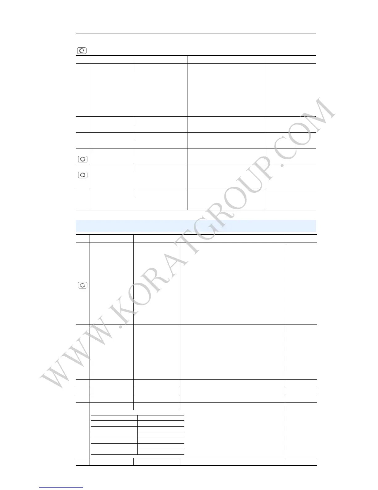
P038 [Speed Reference] 0/5 0 = “Drive Keypad”
1 = “InternalFreq”
2 = “Analog In 1”
3 = “Analog In 2”
4 = “Preset Freq”
5 = “Comm Port”
2
Sets the source of the speed reference to the drive.
Important: When T051 – T054 [Digital Inx Sel] is
set to option 1, 2, 3, 4, 5, 8, 14, 15, 16 or 17 and
the digital input is active, or if A152 [PID Ref Sel] is
not set to option 0, the speed reference
commanded by this parameter will be overridden.
Refer to Chapter 1 of the PowerFlex 400 User
Manual for details.
P039 [Accel Time 1] 0.00/600.00 Secs 0.01 Secs 20.00 Secs
Sets the rate of accel for all speed increases.
P040 [Decel Time 1] 0.00/600.00 Secs 0.01 Secs 20.00 Secs
Sets the rate of decel for all speed decreases.
P041 [Reset To Defalts] 0/1 0 = “Ready/Idle”
1 = “Factory Rset”
0
Resets all parameter values to factory defaults.
P042 [Auto Mode] 0/3
0 = “No Function”
1 = “Hnd-Off-Auto”
2 = “Local/Remote”
3 = “Auto/Manual”
1
Determines the operation of the “Auto” key on the
integral keypad.
P043 [Motor OL Ret] 0/1 0 = “Disabled”
1 = “Enabled”
0 = “Disabled”
Enables/disables the Motor Overload Retention
function.
= Stop drive before changing this parameter.
No. Parameter Min/Max Display/Options Default
Terminal Block Group Parameters
No. Parameter Min/Max Display/Options Default
T051
T052
T053
T054
[Digital In1 Sel]
I/O Terminal 05
[Digital In2 Sel]
I/O Terminal 06
[Digital In3 Sel]
I/O Terminal 07
[Digital In4 Sel]
I/O Terminal 08
0/36 0 = “Not Used”
1 = “Purge”
2 = “Auto Mode”
3 = “Local”
4 = “Comm Port”
5 = “PID Disable”
6 = “PID Hold”
7 = “PID Reset”
8 = “Preset Freq”
9 = “Aux Fault”
10 = “Clear Fault”
11 = “RampStop,CF”
12 = “CoastStop,CF”
13 = “DCInjStop,CF”
14 = “Anlg1 InCtrl”
15 = “Anlg2 InCtrl”
16 = “MOP Up”
17 = “MOP Down”
18 = “Acc & Dec 2”
19 = “Current Lmt2”
20 = “Force DC”
21 = “Mtr I-Lock 1”
22 = “Mtr I-Lock 2”
23 = “Mtr I-Lock 3”
24 = “Mtr I-Lock 4”
25 = “Cmd Reverse”
31 = “Logic In 1”
32 = “Logic In 2”
36 = “Damper Input”
1
3
10
4
T055
T060
[Relay Out1 Sel]
[Relay Out2 Sel]
0/23 0 = “Ready/Fault”
1 = “At Frequency”
2 = “MotorRunning”
3 = “Hand Active”
4 = “Motor Overld”
5 = “Ramp Reg”
6 = “Above Freq”
7 = “Above Cur”
8 = “Above DCVolt”
9 = “Above Anlg 2”
10 = “Above PF Ang”
11 = “Anlg In Loss”
12 = “ParamControl”
13 = “Retries Exst”
14 = “NonRec Fault”
15 = “Reverse”
16 = “Logic In 1”
17 = “Logic In 2”
23 = “Aux Motor”
0
2
T056 [Relay Out1 Level] 0.0/9999 0.1 0.0
T058 [Relay 1 On Time] 0.0/600.0 Secs 0.1 Secs 0.0 Secs
T059 [Relay 1 Off Time] 0.0/600.0 Secs 0.1 Secs 0.0 Secs
T061 [Relay Out2 Level] 0.0/9999 0.1 0.0
T063 [Relay 2 On Time] 0.0/600.0 Secs 0.1 Secs 0.0 Secs

 Loading...


