PowerFlex 400 Adjustable Frequency AC Drive Quick Start English-25
To clear a fault, press the Stop key, cycle power or set A100 [Fault Clear] to 1 or
2.
For a complete listing of Faults and Alarms, refer to the PowerFlex 400
User Manual.
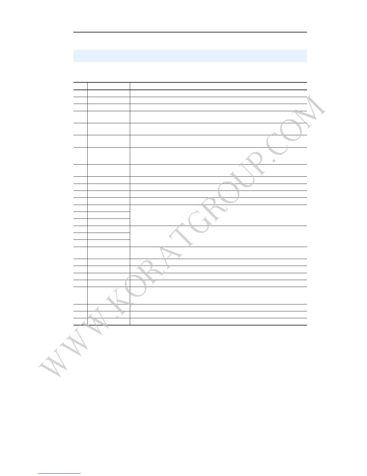
Fault Codes
No. Fault Description
F2 Auxiliary Input
(1)
Check remote wiring.
F3 Power Loss Monitor the incoming AC line for low voltage or line power interruption.
F4 UnderVoltage
(1)
Monitor the incoming AC line for low voltage or line power interruption.
F5 OverVoltage
(1)
Monitor the AC line for high line voltage or transient conditions. Bus overvoltage can also be
caused by motor regeneration. Extend the decel time or install a dynamic brake chopper.
F6 Motor Stalled
(1)
Increase [Accel Time x] or reduce load so drive output current does not exceed the current set
by parameter A089 [Current Limit].
F7 Motor Overload
(1)
An excessive motor load exists. Reduce load so drive output current does not exceed the
current set by parameter P033 [Motor OL Current].
F8 Heatsink OvrTmp
(1)
Check for blocked or dirty heat sink fins. Verify that ambient temperature has not exceeded 40°C
(104°F) for IP 30/NEMA 1/UL Type 1 installations or 50°C (122°F) for Open type installations.
Check fan.
F12 HW OverCurrent Check programming. Check for excess load, improper DC boost setting, DC brake volts set too
high or other causes of excess current.
F13 Ground Fault Check the motor and external wiring to the drive output terminals for a grounded condition.
F15 Load Loss Check for load loss (i.e., a broken belt).
F29 Analog Input Loss
(1)
An analog input is configured to fault on signal loss. A signal loss has occurred.
F33 Auto Rstrt Tries Correct the cause of the fault and manually clear.
F38 Phase U to Gnd Check the wiring between the drive and motor. Check motor for grounded phase.
Replace drive if fault cannot be cleared.
F39 Phase V to Gnd
F40 Phase W to Gnd
F41 Phase UV Short Check the motor and drive output terminal wiring for a shorted condition.
Replace drive if fault cannot be cleared.
F42 Phase UW Short
F43 Phase VW Short
F48 Params Defaulted The drive was commanded to write default values to EEPROM. Clear the fault or cycle power to
the drive. Program the drive parameters as needed.
F63 SW OverCurrent
(1)
Check load requirements and A098 [SW Current Trip] setting.
F64 Drive Overload Reduce load or extend Accel Time.
F70 Power Unit Cycle power. Replace drive if fault cannot be cleared.
F71 Net Loss The communication network has faulted.
F81 Comm Loss If adapter was not intentionally disconnected, check wiring to the port. Replace wiring, port
expander, adapters or complete drive as required. Check connection. An adapter was
intentionally disconnected. Turn off using C105 [Comm Loss Action].
F94 Function Loss Close input to terminal 01 and re-start the drive.
F100 Parameter Checksum Restore factory defaults.
F122 I/O Board Fail Cycle power. Replace drive if fault cannot be cleared.
(1)
Auto-Reset/Run type fault. Configure with parameters A092 and A093.

 Loading...


