English-18 PowerFlex 400 Adjustable Frequency AC Drive Quick Start
The Basic Program Group contains the most commonly changed parameters.
The PowerFlex 400 is designed so that start up is simple and efficient. The Program Group
contains the most commonly used parameters.
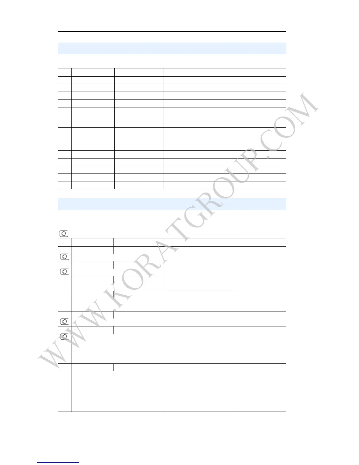
Basic Display Group Parameters
No. Parameter Min/Max Display/Options
b001 [Output Freq] 0.00/[Maximum Freq] 0.01 Hz
b002 [Commanded Freq] 0.00/[Maximum Freq] 0.01 Hz
b003 [Output Current] 0.0/(Drive Amps × 2) 0.1 Amps
b004 [Output Voltage] 0/510 1 VAC
b005 [DC Bus Voltage] 0/820 1 VDC
b006 [Drive Status] 0/1 (1 = Condition True) Bit 4
Bit 3 Bit 2 Bit 1
Decelerating Accelerating Forward Running
b007 [Fault 1 Code] 0/122 1
b008 [Process Display] 0.00/9999.99 0.01
b010 [Output Power] 0.0/999.9 kW 0.1 kW
b011 [Elapsed MWh] 0/3276.7 MWh 0.1 MWh
b012 [Elapsed Run Time] 0/9999 Hrs 1 = 10 Hrs
b013 [Torque Current] 0.0/(Drive Amps × 2) 0.1 Amps
b014 [Drive Temp] 0/120 degC 1 degC
b015 [Elapsed kWh] 0.0/100.0 kWh 0.1 kWh
Smart Start-Up with Basic Program Group
= Stop drive before changing this parameter.
No. Parameter Min/Max Display/Options Default
P031 [Motor NP Volts] 20/Drive Rated Volts 1 VAC Based on Drive Rating
Set to the motor nameplate rated volts.
P032 [Motor NP Hertz] 15/320 Hz 1 Hz 60 Hz
Set to the motor nameplate rated frequency.
P033 [Motor OL Current] 0.0/(Drive Amps × 2) 0.1 Amps Based on Drive Rating
Set to the maximum allowable motor current.
P034 [Minimum Freq] 0.0/320.0 Hz 0.1 Hz 0.0 Hz
Sets the lowest frequency the drive will output
continuously.
P035 [Maximum Freq] 0.0/320.0 Hz 0.1 Hz 60.0 Hz
Sets the highest frequency the drive will output.
P036 [Start Source] 0/6 0 = “Keypad”
1 = “3-Wire”
2 = “2-Wire”
3 = “2-W Lvl Sens”
4 = “2-W Hi Speed”
5 = “Comm Port”
6 = “2-W Lvl/Enbl”
3
Sets the control scheme used to start the drive
when in Auto/Remote mode.
P037 [Stop Mode] 0/7 0 = “Ramp, CF”
(1)
1 = “Coast, CF”
(1)
2 = “DC Brake, CF”
(1)
3 = “DCBrkAuto,CF”
(1)
4 = “Ramp”
5 = “Coast”
6 = “DC Brake”
7 = “DC BrakeAuto”
(1)
Stop input also clears active fault.
0
Active stop mode for all stop sources [e.g. keypad,
run forward (I/O Terminal 02), run reverse (I/O
Terminal 03), RS485 port] except as noted below.
Important: I/O Terminal 01 is always a coast to
stop input except when P036 [Start Source] is set
for “3-Wire” control. When in three wire control, I/O
Terminal 01 is controlled by P037 [Stop Mode].

 Loading...


