English-12 PowerFlex 400 Adjustable Frequency AC Drive Quick Start
Relay Terminal Designations and DIP Switches
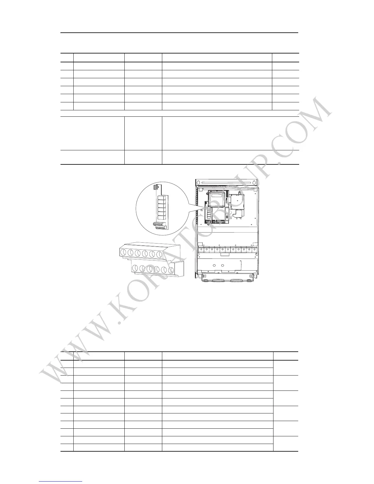
Figure 4: User Installed Auxiliary Relay Card (Frames D, E, & F Only)
Important: If using auxiliary motor control, ensure that wiring and parameter
configuration are correct before wiring contactor outputs. All relays
on the Auxiliary Relay Card will energize on power-up by default.
Failure to verify proper wiring and parameter configuration can result
in improper motor operation or drive damage. Refer to Appendix D
for more details.
User Installed Relay Board Terminal Designations
No. Signal Default Description Param.
R1 #1 Relay N.O. Ready/Fault Normally open contact for No. 1 output relay. T055
R2 #1 Relay Common – Common for output relay.
R3 #1 Relay N.C. Ready/Fault Normally closed contact for No. 1 output relay. T055
R4 #2 Relay N.O. Motor Running Normally open contact for No. 2 output relay. T060
R5 #2 Relay Common – Common for output relay.
R6 #2 Relay N.C. Motor Running Normally closed contact for No. 2 output relay. T060
Selection DIP Switches:
Analog Input (AI1 & AI2)
Analog Output (AO1 & AO2)
0-10V Sets analog output to either voltage or current.
Settings must match: AI1 & T069 [Analog In 1 Sel]
AI2 & T073 [Analog In 2 Sel]
AO1 & T082 [Analog Out1 Sel]
AO2 & T085 [Analog Out2 Sel]
Sink/Source DIP Switch Source (SRC) Inputs can be wired as Sink (SNK) or Source (SRC) via DIP
Switch setting.
No. Signal Default Description Param.
3A #3 Relay N.O. Ready/Fault Normally open contact for Number 3 Output Relay R221
3B #3 Relay Common – Common for Number 3 Output Relay
4A #4 Relay N.O. Ready/Fault Normally open contact for Number 4 Output Relay R224
4B #4 Relay Common – Common for Number 4 Output Relay
5A #5 Relay N.O. Ready/Fault Normally open contact for Number 5 Output Relay R227
5B #5 Relay Common – Common for Number 5 Output Relay
6A #6 Relay N.O. Ready/Fault Normally open contact for Number 6 Output Relay R230
6B #6 Relay Common – Common for Number 6 Output Relay
7A #7 Relay N.O. Ready/Fault Normally open contact for Number 7 Output Relay R233
7B #7 Relay Common – Common for Number 7 Output Relay
8A #8 Relay N.O. Ready/Fault Normally open contact for Number 8 Output Relay R236
8B #8 Relay Common – Common for Number 8 Output Relay

 Loading...


