Programming and Parameters 3-23
PowerFlex 4M Adjustable Frequency Drive FRN 1.xx - 2.xx User Manual
Publication 22F-UM001D-EN-E
Advanced Program Group (continued)
A425 [DC Brake Level] Related Parameter(s): P107, A418
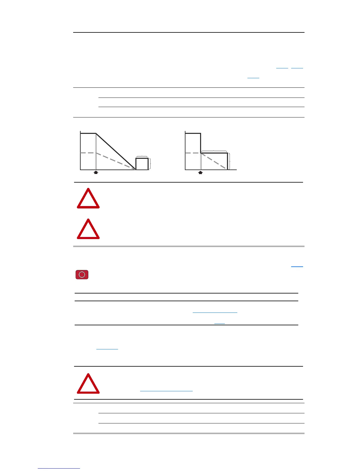
Defines the maximum DC brake current, in amps, applied to the motor when P107 [Stop Mode] is set
to either “Ramp” or “DC Brake”.
Values Default Drive Rated Amps × 0.05
Min/Max: 0.0/(Drive Rated Amps × 1.8)
Display: 0.1 Amps
DC Injection Brakin
ATTENTION: If a hazard of injury due to movement of equipment or material exists,
an auxiliary mechanical braking device must be used.
ATTENTION: This feature should not be used with synchronous or permanent
magnet motors. Motors may be demagnetized during braking.
A427 [DB Resistor Sel] Related Parameter(s): A428
Stop drive before changing this parameter.
Enables/disables external dynamic braking. This
parameter applies only to Frame C drives.
The drive is able to provide full braking indefinit
ely. Braking power is limited by the external DB
resistor. When this parameter is set to 1 “Normal RA Res” and an appropriate RA resistor is used (see
selection
Table B.C), the drive provides calculated resistor overload protection. However, the drive
cannot protect against a brake IGBT failure.
Values Default 0
Min/Max: 0/3
Display: 1
Setting Min/Max
0
1
2
3
“Disabled”
“Normal RA Res” (5% Duty Cycle) - Refer to Table B.C on page B-2
“No Protection” (100% Duty Cycle)
“% Duty Cycle” Limited (1% – 99% of Duty Cycle) - see A428
ATTENTION: A risk of fire exists if external braking resistors are not protected. The
external resistor package must be self-protected from over temperature or the protective
circuit shown in Figure B.3 on page B-7
, or equivalent, must be supplied.
 Loading...


