48 Rockwell Automation Publication 20A-UM001N-EN-P - July 2013
Chapter 1 Programming and Parameters
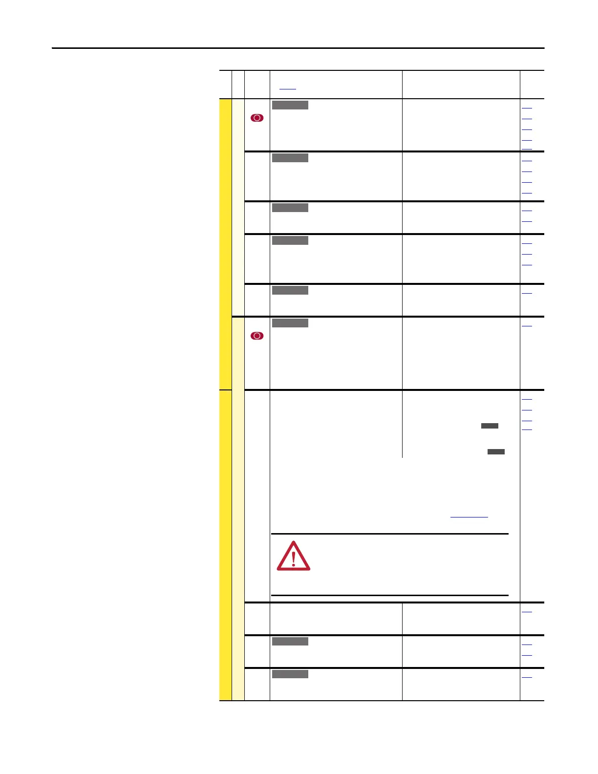
Restart Modes
179 [Sleep Wake Ref]
Selects the source of the input controlling the
Sleep-Wake function.
Default:
Options:
2
1
2
“Analog In 2”
“Analog In 1”
“Analog In 2”
178
180
183
320…
327
180 [Wake Level]
Defines the analog input level that starts the
drive.
Default:
Min/Max:
Units:
6.000 mA, 6.000 Volts
[Sleep Level]/20.000 mA [Sleep
Level]/10.000 Volts
0.001 mA
0.001 Volts
178
179
181
183
181 [Wake Time]
Defines the amount of time at or above [Wake
Level] before a Start is issued.
Default:
Min/Max:
Units:
1.0 Secs
0.0/1000.0 Secs
0.1 Secs
178
180
182 [Sleep Level]
Defines the analog input level that stops the
drive.
Default:
Min/Max:
Units:
5.000 mA, 5.000 Volts
4.000 mA/[Wake Level]
0.000 Volts/[Wake Level]
0.001 mA
0.001 Volts
178
180
183
183 [Sleep Time]
Defines the amount of time at or below [Sleep
Level] before a Stop is issued.
Default:
Min/Max:
Units:
1.0 Secs
0.0/1000.0 Secs
0.1 Secs
182
DYNAMIC CONTROL (file D)
Power Loss
177 [Gnd Warn Level]
Sets the level where a ground warning fault
occurs. Configure with [Alarm Config 1].
Default:
Min/Max:
Units:
3.0 Amps
1.0/5.0 Amps
0.1 Amps
259
184 [Power Loss Mode]
Sets the reaction to a loss of input power. Power
loss is recognized when:
• DC bus voltage is ≤ 73% of [DC Bus Memory]
and [Power Loss Mode] is set to “Coast”.
• DC bus voltage is ≤ 82% of [DC Bus Memory]
and [Power Loss Mode] is set to “Decel”.
Default:
Options:
0
0
1
2
3
4
5
“Coast”
“Coast”
“Decel”
“Continue”
“Reserved”
“Reserved”
“Decel 2 Stop”
013
185
361…
366
“Coast” = Disable drive and enable the motor to coast.
“Decel” = Decelerate the motor at a rate that regulates the DC Bus until the load’s Kinetic
Energy can no longer power the drive.
“Continue” = Enable the drive to power the motor down to 50% of the nominal DC Bus
voltage.
Refer to the PowerFlex 70EC/700VC Reference Manual, publication PFLEX-RM004
, for
additional information.
185 [Power Loss Time]
Sets the time that the drive remains in power
loss mode before a fault is issued.
Default:
Min/Max:
Units:
0.5 Secs
0.0/60.0 Secs
0.1 Secs
184
187 [Load Loss Level]
Sets the percentage of motor nameplate torque
where a load loss alarm occurs.
Default:
Min/Max:
Units:
200.0%
0.0/800.0%
0.1%
211
259
188 [Load Loss Time]
Sets the time that current is below the level set
in [Load Loss Level] before a fault occurs.
Default:
Min/Max:
Units:
0.0 Secs
0.0/300.0 Secs
0.1 Secs
187
File D
Group
No.
Parameter Name and Description
See page 14 for symbol descriptions
Values
Related
E C v2
E C v2
E C v2
E C v2
E C v2
E C v2
E C v4
ATTENTION: To guard against drive damage, a minimum line
impedance must be provided to limit inrush current when the
power line recovers. Provide an input impedance equal or
greater than the equivalent of a 5% transformer with a VA rating
6 times the drive’s input VA rating.
E C v2
E C v2
 Loading...


