Component Test Procedures 2-11
1. Locate the fiber optic receiver which transmits the signals for the U
High (UH) gate interface and connector X10 on the Gate Driver board.
X10 provides the gate interface for the UH output power transistor in
the U Phase Output Power module.
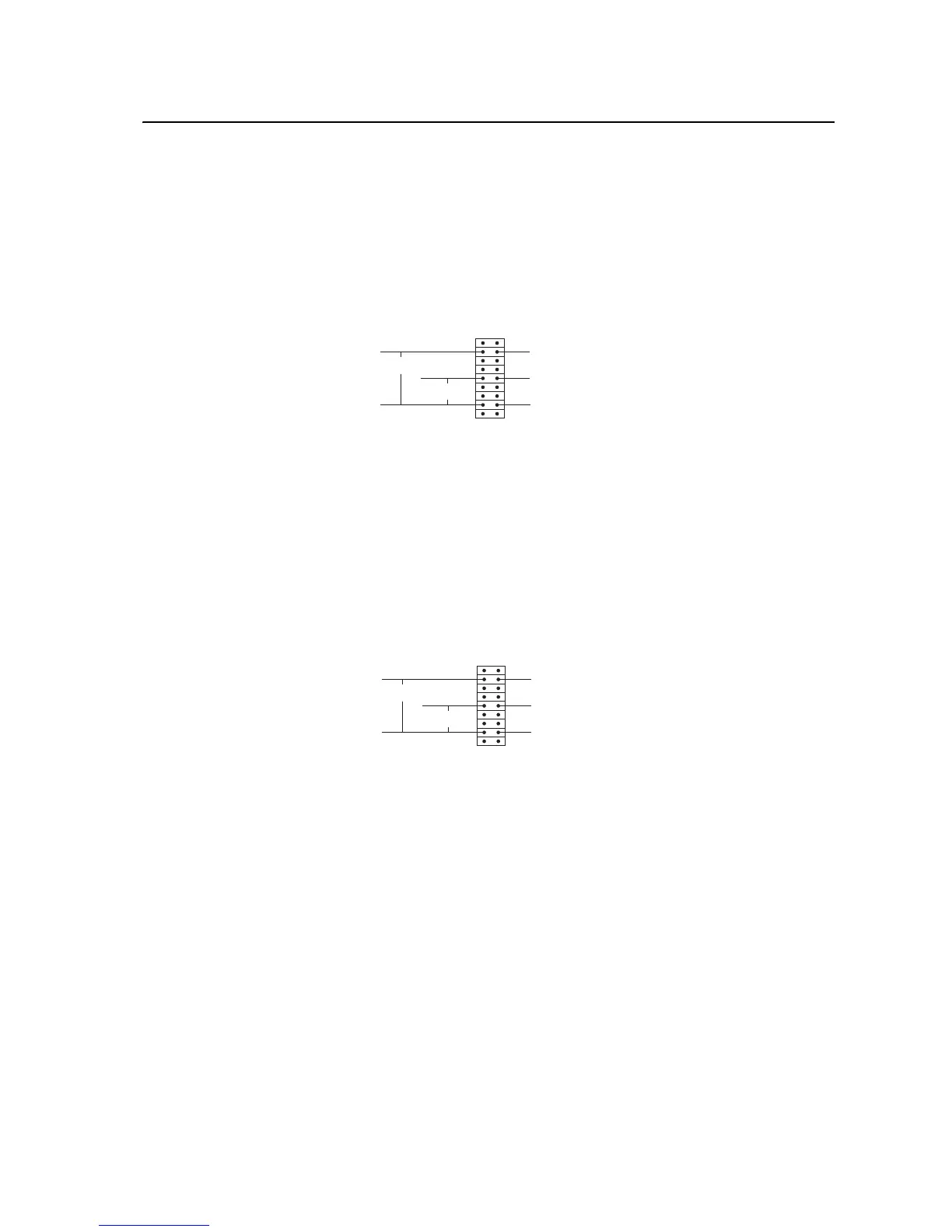
2. Measure the DC voltage at each UH gate pin and the emitter pin on X10
by placing the DC- common probe on the emitter pin and the voltage
probe on the gate pins.
3. While shining an intense light (like a flashlight) into the fiber optic
receiver for the UH cable, measure the DC voltage at each UH gate pin
and the emitter pin on X10 with respect to DC-. Each should be +15V
dc. If the drive fails any of these tests, replace the fiber optic cable or the
Gate Driver board.
4. Repeat steps 2 and 3 with connector X11 and the UL cable. X11
provides the gate interface for the UL output power transistor in the U
Phase Output Power module. If the drive fails any of these tests, replace
the Gate Driver board.
5. Repeat steps 2 and 3 with connector X10 and the VH cable. X10
provides the gate interface for the VH output power transistor in the V
Phase Output Power module. If the drive fails any of these tests, replace
the Gate Driver board.
6. Repeat steps 2 and 3 with connector X11 and the VL cable. X11
provides the gate interface for the VL output power transistor in the V
Phase Output Power module. If the drive fails any of these tests, replace
the Gate Driver board.
7. Repeat steps 2 and 3 with connector X10 and the WH cable. X10
provides the gate interface for the WH output power transistor in the W
Phase Output Power module. If the drive fails any of these tests, replace
the Gate Driver board.
8. Repeat steps 2 and 3 with connector X11 and the WL cable. X11
provides the gate interface for the WL output power transistor in the W
DC+ Voltage Probe
DC- Common Probe
X10
DC+ Voltage Probe
+15V DC
+15V DC
DC+ Voltage Probe
DC- Common Probe
X11
DC+ Voltage Probe
+15V DC
+15V DC

 Loading...


