Access Procedures 3-11
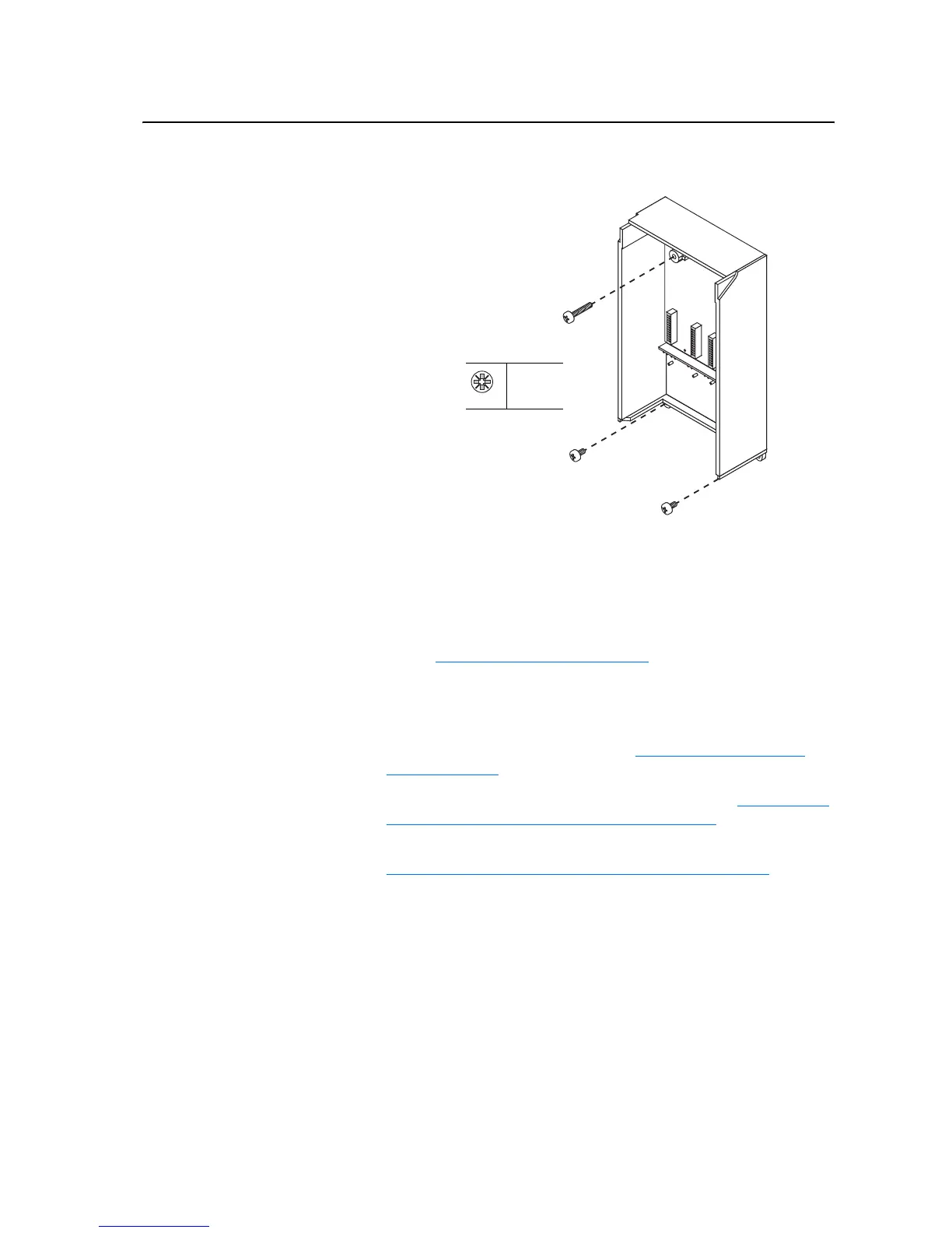
5. Remove the three screws which secure the Control Assembly to the
drive.
6. Remove the Control Assembly.
Installation
Install the 700H Control and I/O Boards in reverse order of removal, while
referring to Torque Specifications on page 3-1
.
Removing the 700H Fiber
Optic Adapter Board
Removal
1. Remove power from the drive. Refer to Removing Power from the
Drive on page 3-3.
2. Remove the I/O boards and Control Assembly. Refer to Removing the
700H I/O Boards and Control Assembly on page 3-9.
3. Move the Control Frame to expose its back, while referring to
Removing the Covers from the Power Structure on page 3-13
.
Do not remove enclosure cover.
Enclosure is illustrated without
the cover for clarity.
PZ2
3 N-m
(27 lb.-in.)

 Loading...


