3-12 Access Procedures
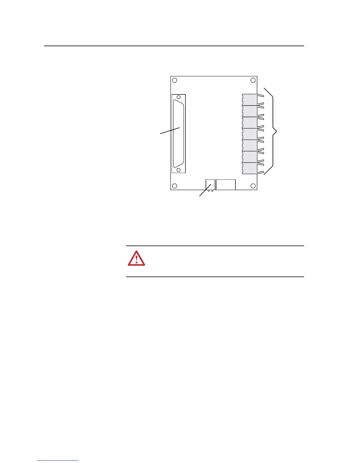
4. Disconnect the control power cable from X2 of the Fiber Optic Adapter
Board.
5. Carefully disconnect the fiber-optic cables from the right side of the
circuit board, and carefully set them aside.
Important: Minimum inside bend radius for fiber-optic cable is 25.4 mm (1
in.). Any bends with a shorter inside radius can permanently
damage the fiber-optic cable. Signal attenuation increases with
decreased inside bend radii.
!
ATTENTION: Hazard of permanent eye damage exists when
using optical transmission equipment. This product emits intense
light and invisible radiation. Do not look into fiber-optic ports or
fiber-optic cable connectors.
H1
H2
H3
H4
H5
H6
H7
Sockets for
Fiber-Optic
cables
X1 connects
to Main
Control
X2 connects
to 24V dc
power

 Loading...


