Schematics B-9
Circuit Board Connections for 700H Drives with DC Input
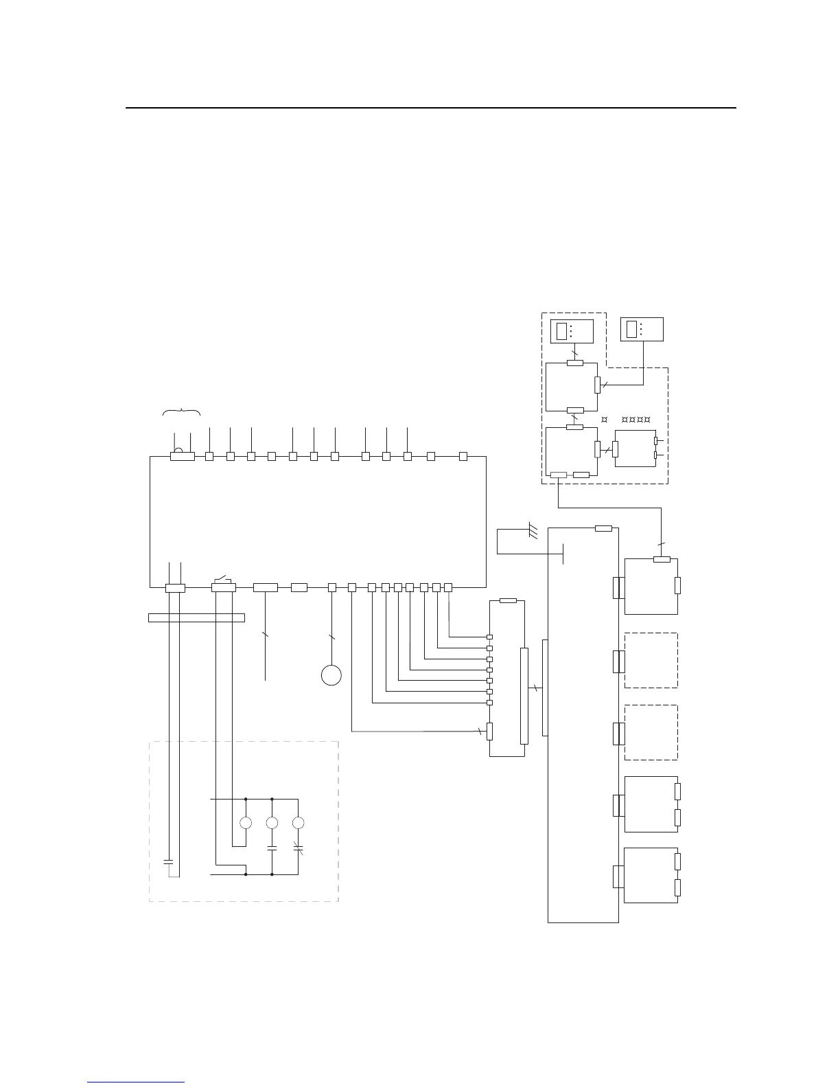
Figure B.8 Circuit Board Connections for
700H Drives with DC Input
frm11_circuit_bd_conns_700H.eps
Fiber Optics
Analog
I/O
3
3
(Slot A)
X2
20C-D01
(Digital Output
Option)
(Slot B)
X3
Control Board
Adapter Board
X4
(Slot C)
Option
Board
(Slot D)
X5
(Slot E)
20C-DPI1
(DPI Communcations
Option)
X1
X3
X6
X2
9
RS-232
Programming
Port
X7
+24V
X3
2
37
X1
H2H1
H3
H5
H4
H6 H7
X4
J3
DPI Assembly
Option
20C-DPI1
Comm
DPI
X3
PORT
NET A
NET B
MOD
20
PWR
EXAMPLE:
20-HIM-A3
EXTERNAL DPI
HIM
9
DOOR
HIM
Bezel
HIM
20-VB00601
DPI
Interface
Board
X2
X1
J2
J1
9
M
ASIC Board Fan
GND
+24V
X2
2
1
X1
Option
Board
20C-DA1-A
(24V dc Digital
Input w/ Analog I/O)
20C-DA1-AB
(115V ac Digital
Input w/ Analog I/O)
CR1
Pilot Relay
CR1
M
Main DC Contactor
M
CR2
Precharge
M
External Precharge Example Circuitry
For DC Input Only (Do Not Install on AC Input Drives)
To Fan Inverter X8
X2
H13
H12
H11
H10
X4
H9
H8
X3
X6
ASIC
Board
X9
X15 Charge Relay
X11 (Fan Control)
X1
25
26
21
22
23
1
2
3
H1
H2
H3
H4
H5
H6
H7
X5
To Phase U Gate Driver Board
X6 in Power Circuitry
To Phase U Gate Driver Board
H15 in Power Circuitry
To Phase U Gate Driver Board
H16 in Power Circuitry
To Phase V Gate Driver Board
X6 in Power Cirucitry
To Phase V Gate Driver Board
H15 in Power Circuitry
To Phase V Gate Driver Board
H16 in Power Circuitry
To Phase W Gate Driver Board
X6 in Power Circuitry
To Phase W Gate Driver Board
H15 in Power Circuitry
To Phase W Gate Driver Board
H16 in Power Circuitry
Fiber Optic Cables
+24V
0EVA
3
2
DC-
DC+
From DC Bus in Power Circuitry
X50
X600
X29
X26
X10 24V Power
1
2
3
4

 Loading...


