Component Test Procedures 2-15
Taking Measurements on Rectifying Module
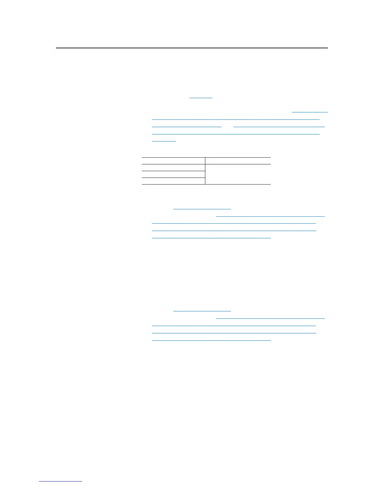
8. Disconnect connectors X13, X12, X11 and X10.
9. Perform resistance measurements, using a digital multimeter, on the
points listed in Table 2.F
below. These points are on the back of the
X10, X11 and X12 plugs which you have disconnected from the board.
If this test fails, replace both Rectifying modules (See Removing the
V Phase (Middle) Rectifying Board, Rectifying Module and Output
Power Module on page 3-33 and Removing the W Phase (Right-Side)
Rectifying Board, Rectifying Module and Output Power Module on
page 3-36).
Table 2.F Rectifying Module Resistance Measurements
10. Without applying power to X13 verify that there is no resistance
between the following points: J3 and X9, J7 and X9, and J11 and X9.
Refer to Table 2.G on page 2-16
. If this test fails, replace both
Rectifying modules (See Removing the V Phase (Middle) Rectifying
Board, Rectifying Module and Output Power Module on page 3-33 and
Removing the W Phase (Right-Side) Rectifying Board, Rectifying
Module and Output Power Module on page 3-36).
Important: Power supply polarity is critical during these tests. Reversing
the polarity will damage components on the circuit board.
11. Connect the DC Test Power Supply to X13 (positive to pin 5 and
common to pin 1). Raise the output of the DC Test Power Supply to
24V dc.
12. Verify that the voltage and resistance between the following points is
zero: J3 and X10: Pin 1, J7 and X11: Pin 1, and J11 and X12: Pin 1.
Refer to Table 2.G on page 2-16
. If this test fails, replace both
Rectifying modules (See Removing the V Phase (Middle) Rectifying
Board, Rectifying Module and Output Power Module on page 3-33 and
Removing the W Phase (Right-Side) Rectifying Board, Rectifying
Module and Output Power Module on page 3-36).
Measurement points Resistance
X10: red to X10: black
18:r:X11: red to X11: black
X12: red to X12: black

 Loading...


