Home
Allen-Bradley
Controller
PowerFlex 700H
Allen-Bradley PowerFlex 700H Service Manual
4
of 1
of 1 rating
115 pages
Give review
Manual
Specs
To Next Page
To Next Page
To Previous Page
To Previous Page
Loading...
3-32
Access Procedures
14.
Remo
ve the scre
ws which secure the Output Power Module to the dri
ve.
15.
Disconnect the Po
wer Module Circuit Board from the Adapter Board.
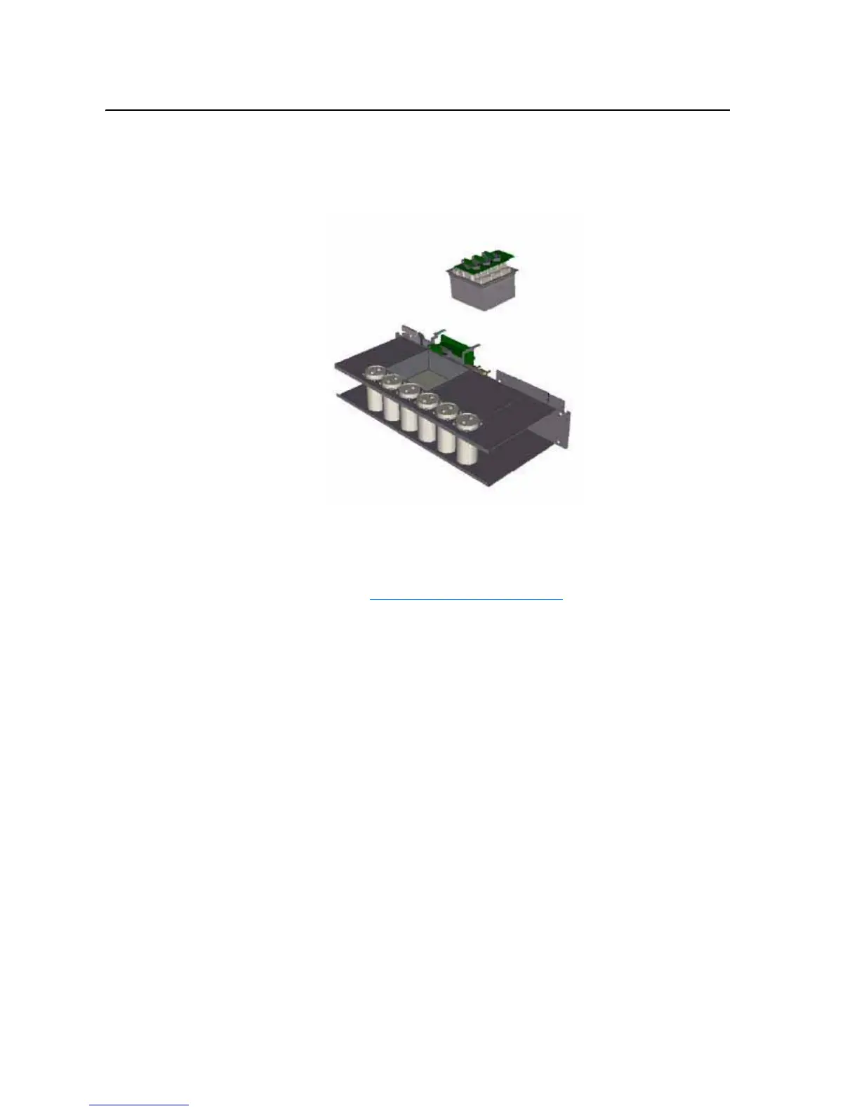
16.
Remo
ve the Output Po
wer Module from the dri
ve.
Installation
Install the Output Po
wer Module in re
verse order of remo
v
al, while
referring to
T
orque Specifications
on page
3-1
.
69
71
Table of Contents
Table of Contents
3
Default Chapter
2
Important User Information
2
Table of Contents
3
Preface
7
What Is in this Manual
7
What Is Not in this Manual
7
Who Should Use this Manual
7
Reference Materials
8
Terms
8
Understanding Manual Conventions
8
Additional Support Available on Internet
9
Cross References
9
Class 1 LED Product
10
General Precautions
10
Chapter 1 Creating Fault Reports
12
Addressing 700S Hardware Faults
12
Addressing 700H Hardware Faults
13
Diagnostic Procedures by Symptom
15
Blown Input Fuses
15
No Output Voltage
16
No HIM Display
17
Over-Temperature Faults
18
Chapter 2 Viewing the 700H Diagnostic LED
19
Viewing the 700S Diagnostic Leds
20
Performing Visual Inspections
22
Inspecting the Cooling Tunnels
22
Inspecting the Power Structure
22
Conducting Forward and Reverse Biased Diode Tests for Major Power Components
22
Checking Fiber Optic Connections to the Gate Driver Boards
25
Conducting Gate Driver Board Measurements
25
Gate Interface Resistance
26
Preparing the Drive for Active Measurements on the Gate Driver Board
26
Checking the Opto-Couplers
28
Checking the Rectifying Module(S) on AC Input Drives
30
Testing 600V AC Input, 460A and 502A Drives
30
Taking Measurements on Rectifying Module
31
Testing 400V AC Input, 590A, 650A or 730A, or 600V AC Input, 590A Drives
32
Taking Measurements on Rectifying Module
33
Checking the DC Bus Capacitors
35
Checking the Main Fan Inverters and Fans
36
Checking Fan Inverter Fuses
36
Checking Inverter Leds
36
Isolating a Faulty Fan Inverter
36
Checking the Main Fan Motors
37
Chapter 3 Torque Specifications
39
Understanding Torque Figures in Assembly Diagrams
41
Removing Power from the Drive
41
Removing Power
41
Removing the DPI / HIM Assembly
42
Removal
42
Installation
43
Installation
45
Removing the 700S Control Assembly
46
Installation
46
Removal
46
Removing the 700S High Power Fiber Optic Interface Circuit Board
47
Installation
47
Installation
49
Removing the Covers from the Power Structure
51
Installation
51
Moving the Control Frame
51
Removing the Airflow Plate
53
Removing the Protective Covers from Power Structure
54
Removal
55
Removing the 700S Voltage Feedback Circuit Board
55
Installation
56
Removing the Gate Driver Board
56
Removal
56
Installation
57
Removing the ASIC Board
58
Removal
58
Installation
59
Removing the Power Structure from the Drive Cabinet
59
Removal
59
Installation
62
Removing the Main Fans
62
Removal
62
Installation
63
Removing the Fan Inverters
63
Removal
63
Removing the U Phase (Left-Side) Output Power Module
67
Removal
67
Installation
70
Module
71
Removal
71
Installation
73
Module
74
Installation
77
Before Applying Power to the Drive
79
Chapter 4 Before Applying Power to the Drive
79
Testing with the External DC Power Supply Without Load (Optional)
80
Performing the Power Circuit Diagnostic Test on a 700S
81
Testing Without a Motor
81
Testing with the Motor
82
Appendix A Software Tools
83
Service Tools
83
Appendix Schematics
85
Appendix B List of Schematic Diagrams
86
Power Wiring Diagrams
86
Phase U Power Circuitry for Drives with AC Input
86
Phase V Power Circuitry for Drives with AC Input
87
Phase W Power Circuitry for Drives with AC Input
88
Phase U Power Circuitry for Drives with DC Input
89
Phase V Power Circuitry for Drives with DC Input
90
Phase W Power Circuitry for Drives with DC Input
91
Circuit Board Connections for 700H Drives with AC Input
92
Control Wiring Diagrams
92
Circuit Board Connections for 700H Drives with DC Input
93
Circuit Board Connections for 700S Drives - Phase II Control with AC Input
94
Circuit Board Connections for 700S Drives - Phase II Control with DC Input
95
Fan Inverter and Main Fan Connections
96
Hardware Connections
104
Appendix C Circuit Board Connections
105
Appendix D Disassembly/Assembly Diagrams and Spare Parts Numbers
105
Other manuals for Allen-Bradley PowerFlex 700H
Hardware Service Manual
120 pages
Programming Manual
116 pages
Installation Instructions
22 pages
4
Based on 1 rating
Ask a question
Give review
Questions and Answers:
Need help?
Do you have a question about the Allen-Bradley PowerFlex 700H and is the answer not in the manual?
Ask a question
Allen-Bradley PowerFlex 700H Specifications
General
Brand
Allen-Bradley
Model
PowerFlex 700H
Category
Controller
Language
English
Related product manuals
Allen-Bradley powerflex 700
198 pages
Allen-Bradley PowerFlex 700S
118 pages
Allen-Bradley PowerFlex 7000
218 pages
Allen-Bradley PowerFlex 700AFE
192 pages
Allen-Bradley PowerFlex 70
132 pages
Allen-Bradley PowerFlex 755
354 pages
Allen-Bradley PowerFlex 755TM
192 pages
Allen-Bradley PowerFlex 755TL
192 pages
PowerFlex 20-750-S1
302 pages
PowerFlex 750 Series
50 pages
PowerFlex 20-750-ENETR
302 pages
PowerFlex 20-750-20COMM
302 pages