Access Procedures 3-31
10. Remove the screws that secure the U Phase (left side) Power assembly
to the drive and remove the Power assembly.
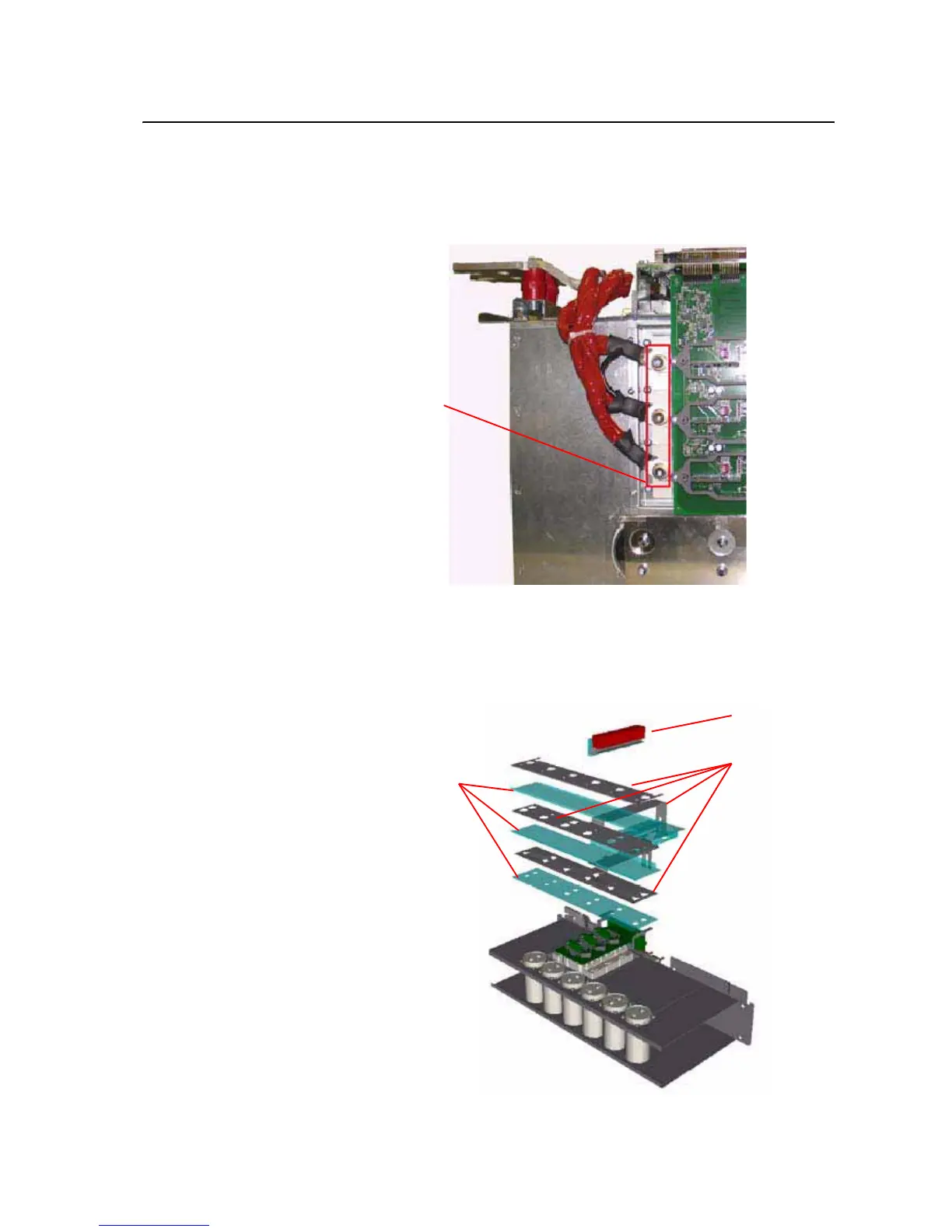
11. Remove the screws that secure the motor connection leads to the Power
Module assembly and remove the motor connection leads.
12. Remove the screws that secure the Snubber Capacitors and remove the
Snubber Capacitors.
13. Remove the screws that secure the DC Bus Bars to the U Phase (left
side) power module and remove the DC Bus Bars.
Motor
Connection
Leads
Snubber
Capacitors
DC Bus Bars
Insulator

 Loading...


