EasyManuals Logo
Home>Allen-Bradley>Controller>PowerFlex 700H

Allen-Bradley PowerFlex 700H Service Manual

Allen-Bradley PowerFlex 700H
115 pages
To Next Page IconTo Next Page
To Previous Page IconTo Previous Page
Page #68 background imageLoading...
Page #68 background image
3-30 Access Procedures
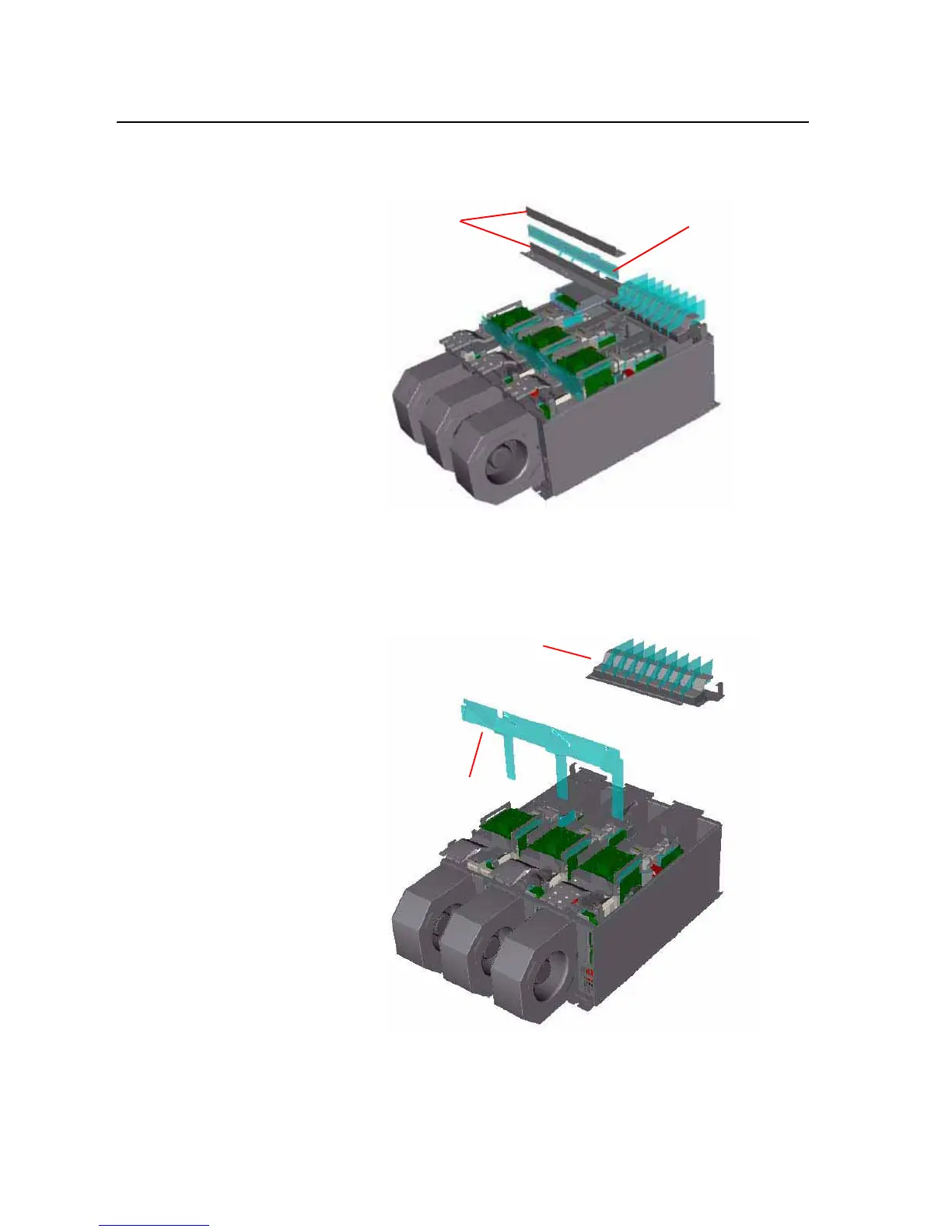
7. Remove the screws that secure the Main DC Bus Bars to the Power
Structure and remove the Main Bus Bars.
8. Remove the screws that secure the Input Power Terminal assembly to
the Power Structure and remove the Input Power Terminal assembly.
9. Remove the screws that secure the Air Flow Guide to the Power
Structure and remove the Air Flow Guide.
DC Bus Bars
Insulator
Input Power Terminal Assembly
Air Flow Guide

Table of Contents

Other manuals for Allen-Bradley PowerFlex 700H

Questions and Answers:

Question and Answer IconNeed help?

Do you have a question about the Allen-Bradley PowerFlex 700H and is the answer not in the manual?

Allen-Bradley PowerFlex 700H Specifications

General IconGeneral
BrandAllen-Bradley
ModelPowerFlex 700H
CategoryController
LanguageEnglish

Related product manuals