3-20 Access Procedures
Removing the ASIC Board
Removal
1. Remove power from the drive. Refer to Removing Power from the
Drive on page 3-3.
2. Remove the covers from the power structures. Refer to Removing the
Covers from the Power Structure on page 3-13.
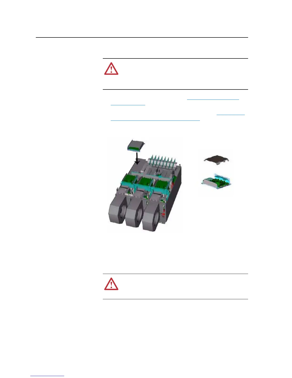
3. Remove the cover from the ASIC assembly and the -DC bus connection
from the cover.
4. Unplug the fan, which mounts on the cover, from connector X1 of the
ASIC board.
5. Carefully disconnect the fiber-optic cables from sockets of the ASIC
Board, and carefully set them aside.
Important: Minimum inside bend radius for fiber-optic cable is 25.4 mm (1
in.). Any bends with a shorter inside radius can permanently
damage the fiber-optic cable. Signal attenuation increases with
decreased inside bend radii.
!
ATTENTION: The sheet metal cover and mounting screws on
the ASIC Board located on the power structure are energized at
(-) DC bus potential high voltage. Risk of electrical shock,
injury, or death exists if someone comes into contact with the
assembly.
!
ATTENTION: Hazard of permanent eye damage exists when
using optical transmission equipment. This product emits intense
light and invisible radiation. Do not look into fiber-optic ports or
fiber-optic cable connectors.

 Loading...


