3-6 Access Procedures
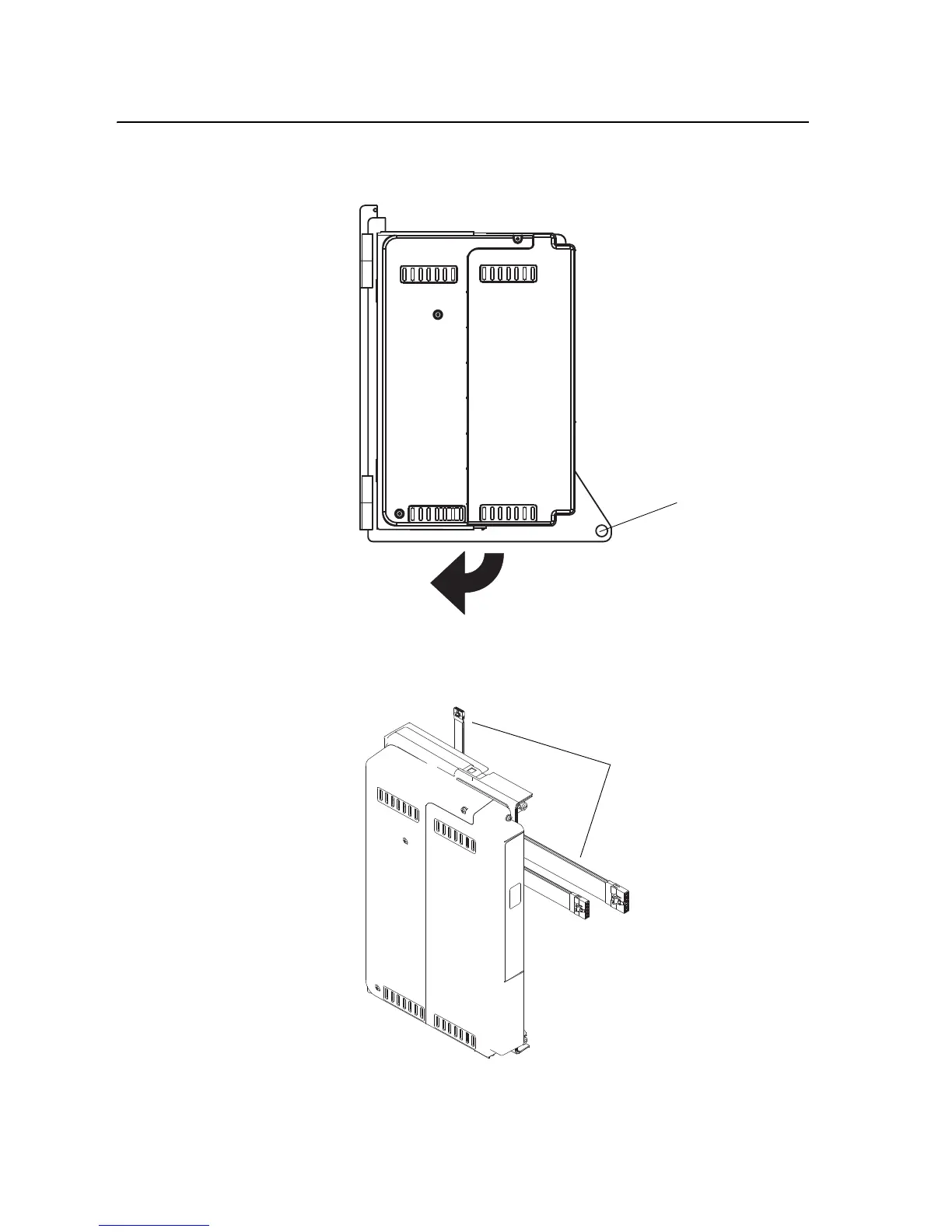
4. Loosen the captive screw on the Control Assembly mounting plate and
swing the Control Assembly away from the drive.
5. Carefully disconnect the ribbon cables from the sockets on the High
Power Fiber Optic Interface Circuit Board on the back of the control
mounting plate, and carefully set them aside.
Captive Screw
Phase II Control Shown
Disconnect ribbon cables.
Note: Control mounting plate
not shown for clarity only.

 Loading...


