EasyManuals Logo

Allen-Bradley PowerFlex 700H Service Manual

Allen-Bradley PowerFlex 700H
115 pages
To Next Page IconTo Next Page
To Previous Page IconTo Previous Page
Page #64 background imageLoading...
Page #64 background image
3-26 Access Procedures
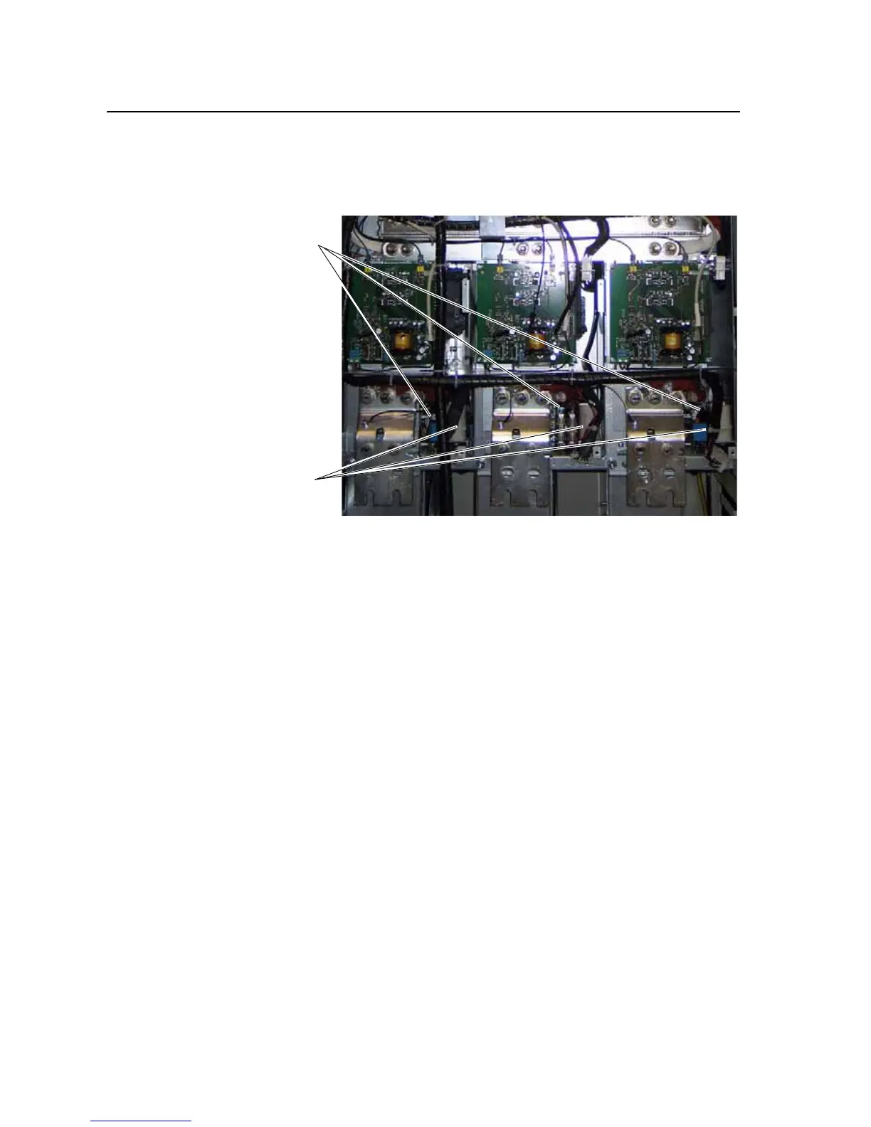
5. Remove the cable-ties that secure the cables with black insulation to the
fan inverter assemblies. This will allow you to move the cables and
remove the inverter assemblies.
6. Disconnect the fan motor cable under the inverter.
7. Remove the four M5 POZIDRIV screws, which secure the bottom of
the fan inverter to the drive. Proper tightening torque for reassembly is 4
N-m (35 lb.-in.).
8. Disconnect the cables at X2, X8 and X3 (on left-hand and center
inverters); and X2 and X8 (on right-hand inverter).
Fan Inverter Locations
Remove cable-ties

Table of Contents

Other manuals for Allen-Bradley PowerFlex 700H

Questions and Answers:

Question and Answer IconNeed help?

Do you have a question about the Allen-Bradley PowerFlex 700H and is the answer not in the manual?

Allen-Bradley PowerFlex 700H Specifications

General IconGeneral
BrandAllen-Bradley
ModelPowerFlex 700H
CategoryController
LanguageEnglish

Related product manuals