3-28 Access Procedures
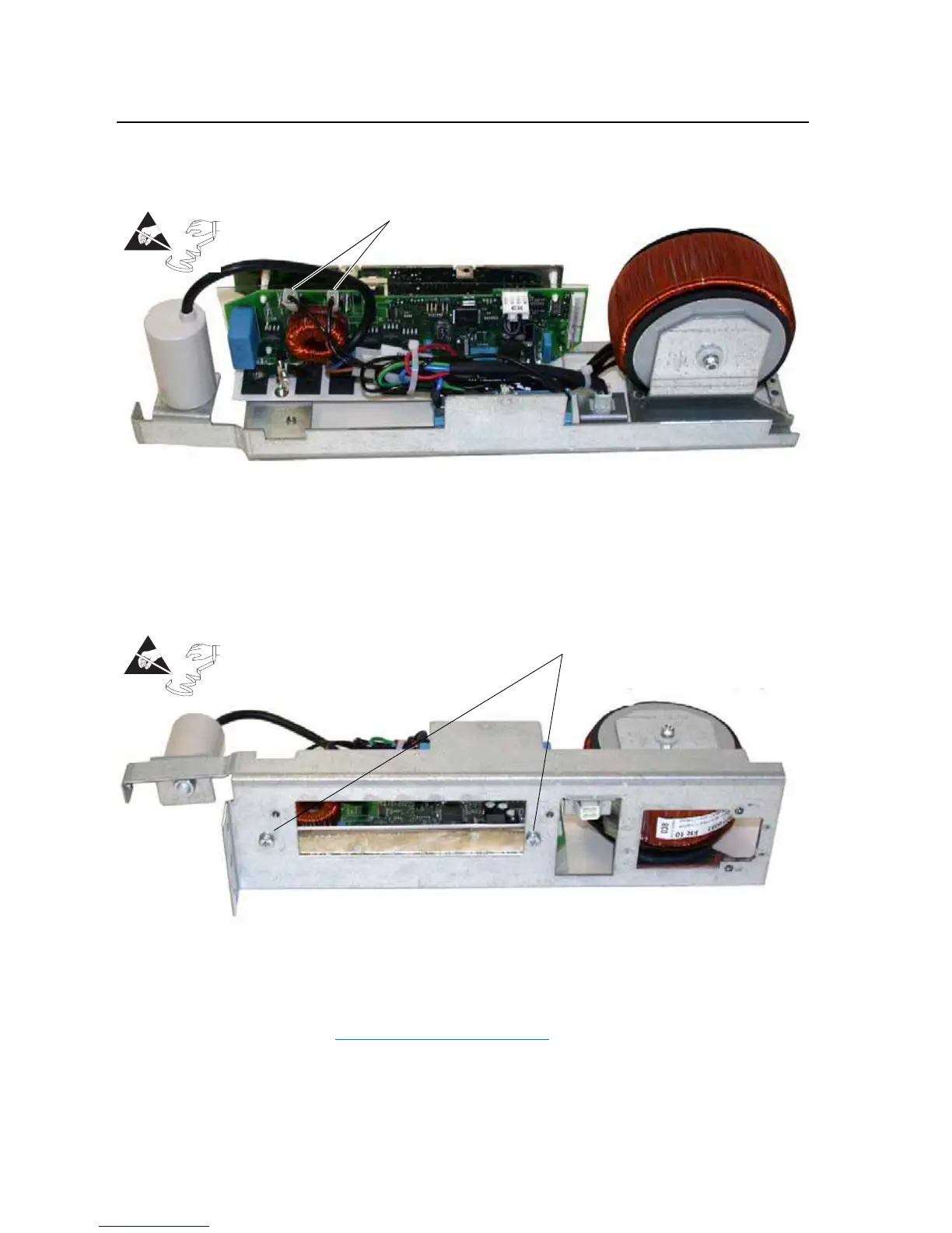
10. To remove the inverter from the old inverter assembly, disconnect the
cables at connectors X4 (Blue) and X5 (Black).
11. Remove two M5 POZIDRIV screws, which secure the inverter board
and its heatsink to the assembly carriage. Proper tightening torque for
reassembly is 4 N-m (35 lb.-in.).
12. Carefully remove the inverter board and its heatsink from the assembly
carriage.
Installation
Install the fan inverters in reverse order of removal, while referring to
Torque Specifications on page 3-1
.
Right-hand Inverter Shown
=
Disconnect X4 and X5
=
Remove two screws and remove inverter
board and heatsink
Right-hand Inverter Shown

 Loading...


