3-34 Access Procedures
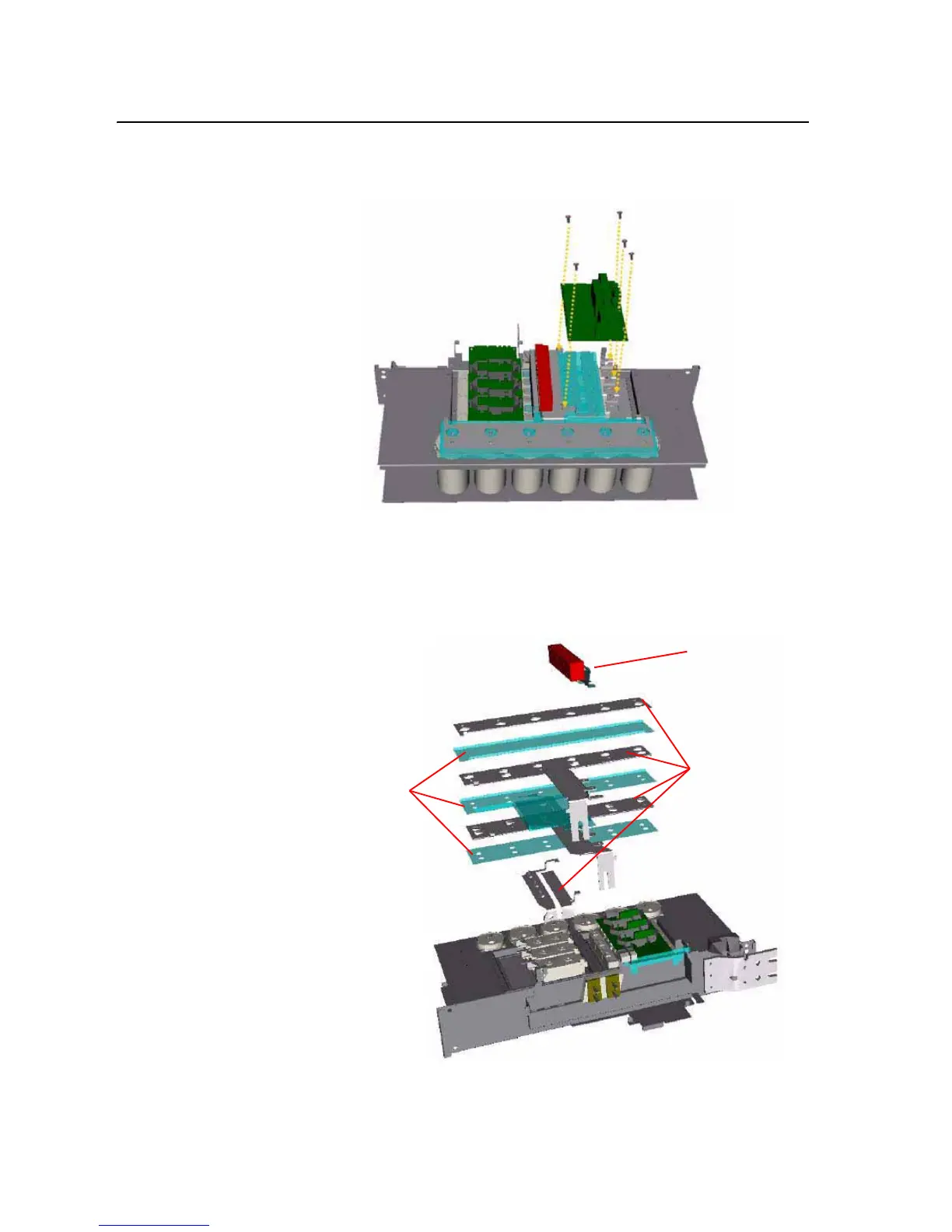
9. Remove the five screws that secure the Rectifying Circuit Board to the
drive and remove the Rectifying Circuit Board.
10. Remove the screws that secure the Snubber Capacitors and remove the
Snubber Capacitors.
11. Remove the screws that secure DC Bus Bars to right side of power
structure, and remove the DC Bus Bars.
Snubber Capacitors
DC Bus Bars
Insulator

 Loading...


