Appendix C
Connector Descriptions
Circuit Board Connections
The following tables detail the connection points for the frame 11
PowerFlex 700S and 700H ac input drives circuit boards and components.
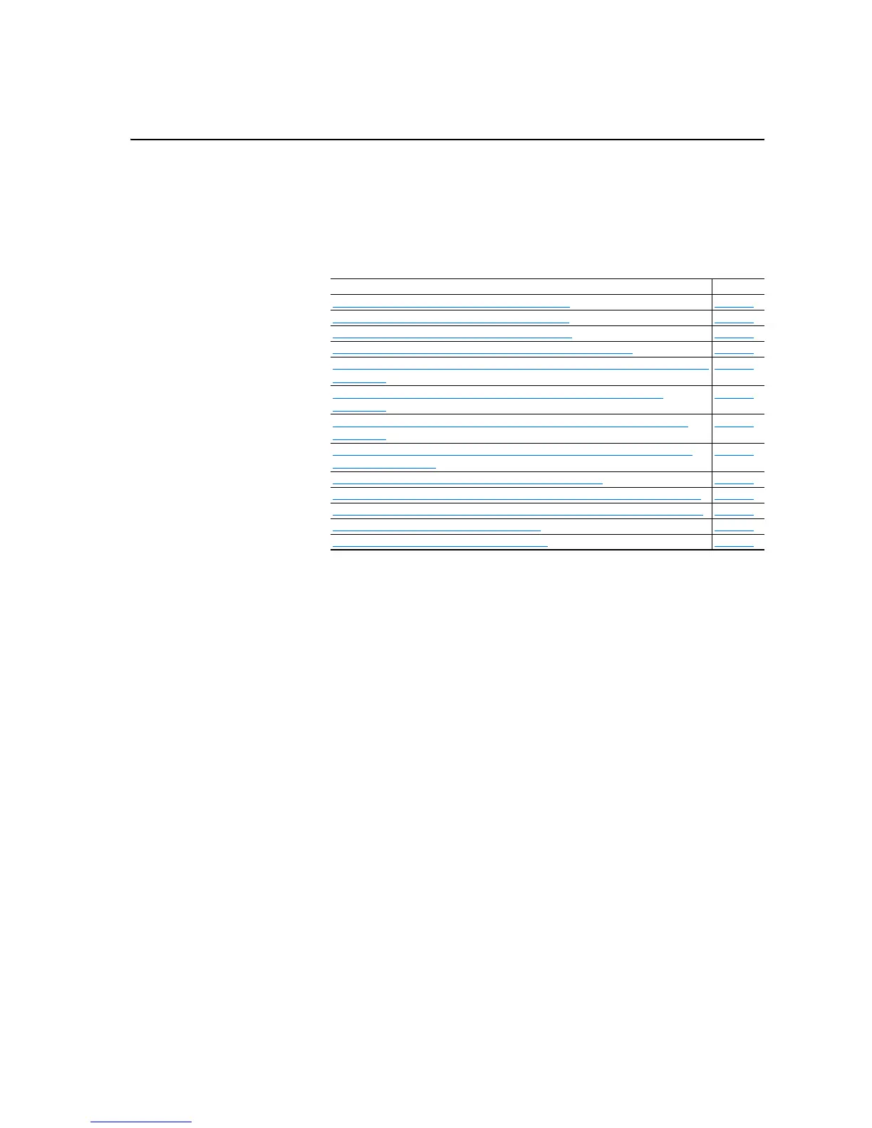
For Information on… See...
ASIC Board to Gate Driver Board Phase U Connections
page C-3
ASIC Board to Gate Driver Board Phase V Connections page C-3
ASIC Board to Gate Driver Board Phase W Connections page C-3
ASIC Board to Rectifier/Precharge Circuit Board Phase V Connections page C-4
Rectifier/Precharge Circuit Board Phase V to Rectifier/Precharge Circuit Board Phase W
Connections
page C-4
PowerFlex 700H Fiber Optic Adapter Circuit Board to ASIC Board Fiber Optic
Connections
page C-5
PowerFlex 700S High Power Fiber Optic Interface Board to ASIC Board Fiber Optic
Connections
page C-6
PowerFlex 700S High Power Fiber Optic Interface Board to Voltage Feedback Board
Fiber Optic Connections
page C-6
ASIC Board to Main Cooling Fan Inverter Phase U Connections page C-7
Main Cooling Fan Inverter Phase U to Main Cooling Fan Inverter Phase V Connections page C-7
Main Cooling Fan Inverter Phase V to Main Cooling Fan Inverter Phase W Connections page C-7
Main Cooling Fan Inverter Phase W Connections page C-7
X50 Terminal Block Precharge Circuit Connections page C-8

 Loading...


