274 Rockwell Automation Publication 750-PM001N-EN-P - February 2017
Chapter 5 Embedded Feature and Option Module Parameters
Universal Feedback
Feedback 0
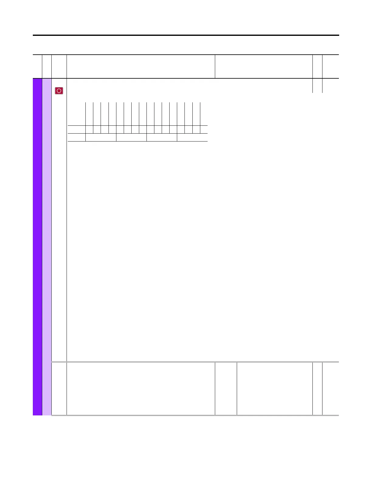
8FB0 Cfg
Feedback 0 Configuration
RW 16-bit
Integer
Configure the direction, position data format, as well as the baud rate for the serial communication interface for the feedback 0 device.
Bit 0 “Direction” – Inverts the direction internally.
Bit 1 “24-bit Resol” – If set, the high resolution 32-Bit feedback position is formatted as 8/24 bit. The 8 refers to the upper 8 most significant bits or left most 8 bits.
These 8 bits count the number of complete encoder shaft revolutions. The remaining lower right least significant 24 bits indicate the encoder position within a
single turn of the encoder shaft. The 24-Bit resolution is only available when Bit 4 “Enh Resol” of the FB Identify parameter is set. If clear, the feedback position is
formatted as 12/20 bit. The upper 12 bits count the number of complete encoder shaft revolutions. The lower 20 bits indicate the encoder position within a single
turn. The 12/20 bit format is the default setting for high resolution feedback.
Bit 2 “FD Low Baud” – Full Digital Low Baud refers to the serial data interface between the encoder and Universal Feedback module. If set, the communication baud
rate is reduced from the default setting for the connected encoder with a serial communication channel. The actual value of the lower baud setting will vary,
depending upon the specific interface and device type in use. For feedback 0, UFB diagnostic item 8 will indicate the exact baud rate in use. For feedback 1,
Universal Feedback diagnostic item 14 will indicate the baud rate. Diagnostic items can be found under “Device Properties” in the “Diagnostics” tab of
DriveExplorer. The possible settings for diagnostic item 8 [Fdbk0 Baud Rate] and item 14 [Fdbk1 Baud Rate] are as follows:
0 = “None” - No digital communication.
1 = “9.6 kBaud” - 9.6 kBaud: Used for communication with Hiperface encoders.
2 = “100 kHz” - 100kHz: Used for communication with
– SSI encoders with sine cosine signals (only in Initialize state).
– Linear SSI encoders if the “Low BaudRate” in [Fdbk0 Pos Config] is set.
3 = “200 kHz” - 200kHz: Used for communication with
– EnDat encoders with sine cosine signals (only in Initialize state).
– BiSS encoders with sine cosine signals (only in Initialize state).
– Linear SSI encoders if the “Low BaudRate” in [Fdbk0 Pos Config] is cleared.
4 = “400 kHz” - Not used.
5 = “1 MHz” - 1MHz: Used for communication with
– SSI encoders if the “Low BaudRate” in [Fdbk0 Pos Config] is set.
6 = “2 MHz” - 2MHz: Used for communication with
– SSI encoders if the “Low BaudRate” in [Fdbk0 Pos Config] is cleared.
– EnDat2.1 encoders without sine cosine signals.
– EnDat2.2 encoders that do not manage 8MHz.
7 = “4 MHz” - 4MHz: Used for communication with
– EnDat2.2 encoders if the “Low BaudRate” in [Fdbk0 Pos Config] is set.
8 = “5 MHz” - 5MHz: Used for communication with
– BiSS encoders if the “Low BaudRate” in [Fdbk0 Pos Config] is set.
9 = “8 MHz” - 8MHz: Used for communication with
– EnDat2.2 encoders if the “Low BaudRate” in [Fdbk0 Pos Config] is cleared.
10 = “10 MHz” - 10MHz: Used for communication with
– BiSS encoders if the “Low BaudRate” in [Fdbk0 Pos Config] is cleared.
Bit 3 “SC Quadrant” – Reserved for future use.
9 FB0 Loss Cfg
Feedback 0 Loss Configuration
Configures how the drive reacts to an error status condition on the feedback 0 device.
“Ignore” (0) – No action is taken.
“Alarm” (1) – Type 1 alarm indicated.
“Flt Minor” (2) – Minor fault indicated. If running, drive continues to run.
Enable with P950 [Minor Flt Cfg]. If not enabled, acts like a major fault.
“FltCoastStop” (3) – Major fault indicated. Coast to Stop.
Default:
Options:
3 = “FltCoastStop”
0 = “Ignore”
1 = “Alarm”
2 = “Flt Minor”
3 = “FltCoastStop”
RW 32-bit
Integer
File
Group
No. Display Name
Full Name
Description
Values
Read-Write
Data Type
Options
Reserved
Reserved
Reserved
Reserved
Reserved
Reserved
Reserved
Reserved
Reserved
Reserved
Reserved
Reserved
SC Quadrant
FD Low Baud
24-bit Resol
Direction
Default0000000000000000
Bit 1514131211109876543210
0 = Condition False
1 = Condition True

 Loading...


