Rockwell Automation Publication 750-PM001N-EN-P - February 2017 487
Using DeviceLogix Appendix D
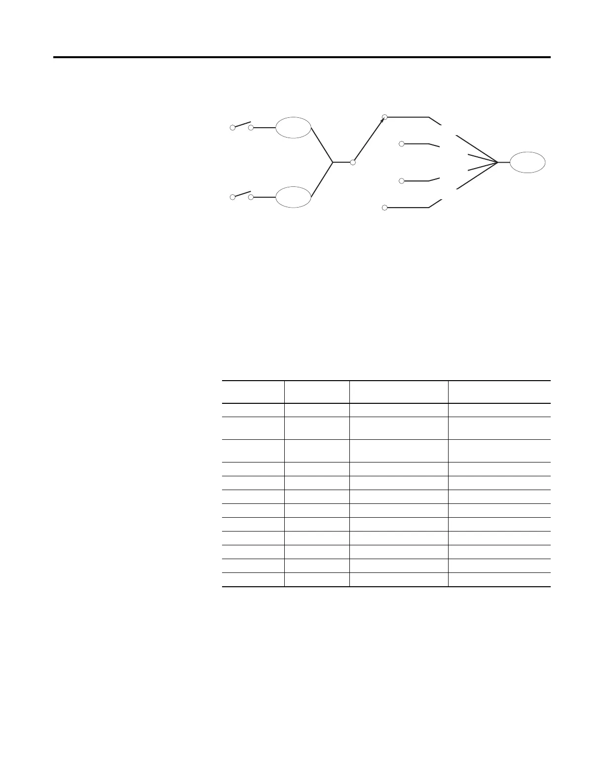
Figure 92 - Two Input Four Position Selector Switch Logic Map
Discrete Inputs in the Drive are used for Inputs 1 and Input 2. Output A, B, C,
and D is linked to DeviceLogix Scratchpad Registers. The scratchpad feature
allows further flexibility to modify the values of these outputs.
The resulting output can be linked to a parameter and be used to support drive
applications, such as configuring multiple preset speeds and point-to-point
positioning. In this example, it controls Preset Speed 1.
Parameter Configuration
The following parameters are configured for this example:
Port Parameter
No.
Parameter Value Description
14.1 DLX Out 01 Port 0: Preset Speed 1
14.33 DLX DIP 1 Port 4: Dig In Status.Input 1 Digital input 1 from Selector
Switch
14.34 DLX DIP 2 Port 4: Dig In Status.Input 2 Digital input 2 from Selector
Switch
14.17 DLX In 01 Port 14: DLX Real SP1 Output A
14.18 DLX In 02 Port 14: DLX Real SP2 Output B
14.19 DLX In 03 Port 14: DLX Real SP3 Output C
14.20 DLX In 04 Port 14: DLX Real SP4 Output D
14.54 DLX Real SP1 75.00 Output A Preset Speed
14.55 DLX Real SP2 85.00 Output B Preset Speed
14.56 DLX Real SP3 95.00 Output C Preset Speed
14.57 DLX Real SP4 105.00 Output D Preset Speed
0.571 Preset Speed 1 varies Output from Selector Switch
Digital Input 1
DLX
DIP 1
Digital Input 2
DLX
DIP 2
DLX
Out 1
00
01
10
11
Output A
Output B
Output C
Output D

 Loading...


