74 Rockwell Automation Publication 750-PM001N-EN-P - February 2017
Chapter 3 Drive Port 0 Parameters
FEEDBACK & I/O
Digital Outputs
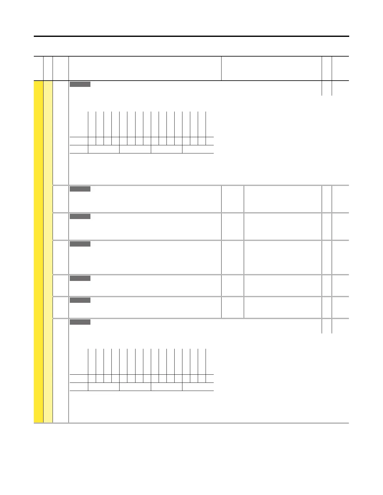
233 RO0 Level CmpSts
Relay Output 0 Level Compensation Status
RO 16-bit
Integer
Status of the level compare, and a possible source for a relay or transistor output. Relay Output n Select or Transistor Output n Select must have this selected to
energize the output. Can be used without a physical output as status information only.
Bit 0 “Less Than” – Level source is less than the level value.
Bit 1 “Grt Than Equ” – Level source is greater than or equal to the level value.
Bit 2 “Abs Less Than” – Absolute value of the level source is less than the absolute value of the level value.
Bit 3 “AbsGrtThanEq” – Absolute value of the level source is greater than or equal to the absolute value of the level value.
234 RO0 On Time
Relay Output 0 On Time
Sets the “ON Delay” time for the digital outputs. This is the time between the occurrence
of a condition and activation of the relay.
Units:
Default:
Min/Max:
Secs
0.00
0.00 / 600.00
RW Real
235 RO0 Off Time
Relay Output 0 Off Time
Sets the “OFF Delay” time for the digital outputs. This is the time between the
disappearance of a condition and de-activation of the relay.
Units:
Default:
Min/Max:
Secs
0.00
0.00 / 600.00
RW Real
240 TO0 Sel
Transistor Output 0 Select
Selects the source that will energize the relay or transistor output.
Any status parameter bit can be used as an output source. For example P935 [Drive
Status 1] Bit 7 “Faulted.”
Default:
Min/Max:
0
0 / 159999.15
RW 32-bit
Integer
241 TO0 Level Sel
Transistor Output 0 Level Select
Selects the source of the level that will be compared.
Default:
Min/Max:
0
0 / 159999
RW 32-bit
Integer
242 TO0 Level
Transistor Output 0 Level
Sets the level compare value.
Default:
Min/Max:
0.0
–/+1000000.0
RW Real
243 TO0 Level CmpSts
Transistor Output 0 Level Compensation Status
RO 16-bit
Integer
Status of the level compare, and a possible source for the transistor output. Transistor Output 0 Select must have this selected to energize the output. Can be used
without a physical output as status information only.
Bit 0 “Less Than” – Level source is less than the level value.
Bit 1 “Grt Than Equ” – Level source is greater than or equal to the level value.
Bit 2 “Abs Less Than” – Absolute value of the level source is less than the absolute value of the level value.
Bit 3 “AbsGrtThanEq” – Absolute value of the level source is greater than or equal to the absolute value of the level value.
File
Group
No. Display Name
Full Name
Description
Values
Read-Write
Data Type
Options
Reserved
Reserved
Reserved
Reserved
Reserved
Reserved
Reserved
Reserved
Reserved
Reserved
Reserved
Reserved
AbsGrtThanEq
Abs Less Than
Grt Than Equ
Less Than
Default0000000000000000
Bit 1514131211109876543210
0 = Condition False
1 = Condition True
Options
Reserved
Reserved
Reserved
Reserved
Reserved
Reserved
Reserved
Reserved
Reserved
Reserved
Reserved
Reserved
AbsGrtThanEq
Abs Less Than
Grt Than Equ
Less Than
Default0000000000000000
Bit 1514131211109876543210
0 = Condition False
1 = Condition True

 Loading...


