Rockwell Automation Publication MOTION-RM003I-EN-P - February 2018 271
The Tuning Speed attribute value determines the maximum speed used by the
Inertia Test service initiated motion profile. This attribute should be set to the
desired maximum operating speed of the motor prior to running the test. The
tuning procedure will measure maximum acceleration and deceleration rates based
on ramps to and from the Tuning Speed. Thus, the accuracy of the measured
acceleration and deceleration capability is reduced by tuning at a speed other than
the desired operating speed of the system.
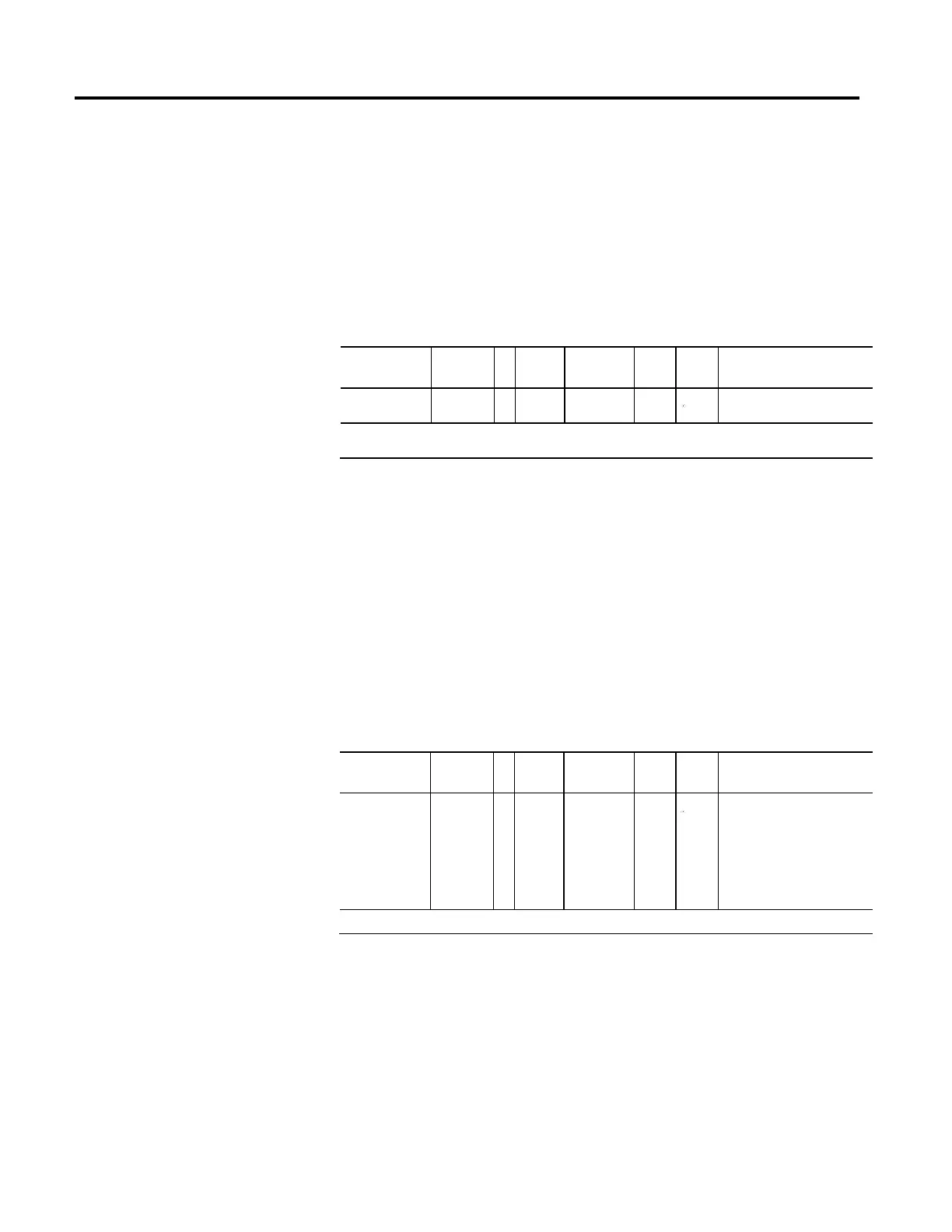
Tuning Torque
Usage Access T Data
Type
Default Min Max Semantics of Values
Required - C SSV#
REAL 100 0
% Rated
# Indicates the attribute cannot be set while the tracking command (Tracking Command bit in CIP Axis Status is true).
The Tuning Torque attribute value determines the maximum torque used by the
Inertia Test service initiated motion profile. This attribute will be set to the
desired maximum safe torque level prior to running the test. The default value is
100%, which yields the most accurate measure of the acceleration and deceleration
capabilities of the system. In some cases a lower tuning torque limit value may be
desirable to limit the stress on the mechanics during the tuning procedure. In this
case the acceleration and deceleration capabilities of the system are extrapolated
based on the ratio of the tuning torque to the maximum torque output of the
system. Note that the extrapolation error increases as the Tuning Torque value
decreases.
Load Ratio
Usage Access T Data
Type
Default Min Max Semantics of Values
Required - C SSV#
REAL 0 0
Rotary Motor:
Load Ratio = (total inertia /
motor inertia) - 1.
Linear Motor:
Load Ratio = (total mass / motor
mass) - 1.
# Indicates the attribute cannot be set while the tracking command (Tracking Command bit in CIP Axis Status is true).
The Load Ratio attribute's value represents the ratio of the load inertia or mass to
the motor inertia or mass.
The value for Load Ratio may be known by the user or may be measured as part of
a software initiated Autotune process.
When Use Load Ratio bit is set in the Gain Tuning Configuration Bits attribute,
configuration software uses the value of Load Ratio to compute Total
Inertia/Mass and System Inertia attributes.

 Loading...


