270 Rockwell Automation Publication MOTION-RM003I-EN-P - February 2018
This enumerated attribute is used by the Auto-tuning software to determine
where the measured inertia results of the test are to be stored. If set to 'motor test',
the measured inertia is stored in the Rotary Motor Inertia attribute or Linear
Motor Mass attribute. If set to 'total inertia', the measured inertia is applied to the
Total Inertia attribute or Total Mass attribute.
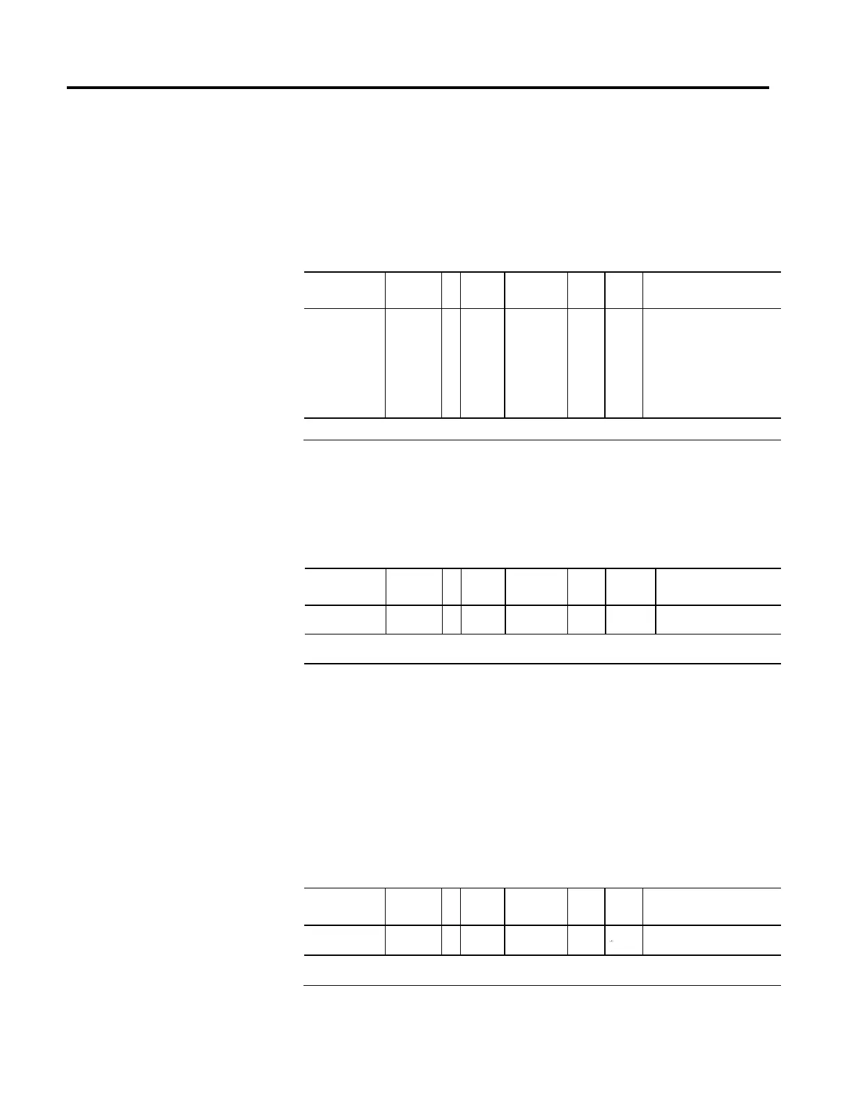
Tuning Direction
Usage Access T Data
Type
Default Min Max Semantics of Values
Required - C SSV#
USINT 0 - - Enumeration
0 = Unidirectional Forward
1 = Unidirectional Reverse
2 = Bidirectional Forward
3 = Bidirectional Reverse
4...255 = Reserved
# Indicates the attribute cannot be set while the tracking command (Tracking Command bit in CIP Axis Status is true).
This enumerated value determines the direction of the motion profile initiated by
the Inertia Test service associated with the Motion Run Axis Tuning (MRAT)
instruction.
Tuning Travel Limit
Usage Access T Data
Type
Default Min Max Semantics of Values
Required - C SSV#
REAL 0 0 maxpos Position Units
# Indicates the attribute cannot be set while the tracking command (Tracking Command bit in CIP Axis Status is true).
The Tuning Travel Limit attribute is used by the Inertia Test service, associated
with the MRAT instruction, to limit the excursion of the axis during the test. If,
while performing the Inertia Test motion profile, the drive determines that the
axis will not be able to complete the profile before exceeding the Tuning Travel
Limit, the drive will terminate the profile and report that the Tuning Travel Limit
was exceeded through the Tune Status attribute. This does not mean that the
Tuning Travel Limit was actually exceeded, but that had the tuning process gone
to completion that the limit would have been exceeded.
Tuning Speed
Usage Access T Data
Type
Default Min Max Semantics of Values
Required - C SSV#
REAL 0 0
Position Units / Sec
# Indicates the attribute cannot be set while the tracking command (Tracking Command bit in CIP Axis Status is true).

 Loading...


