Rockwell Automation Publication MOTION-RM003I-EN-P - February 2018 417
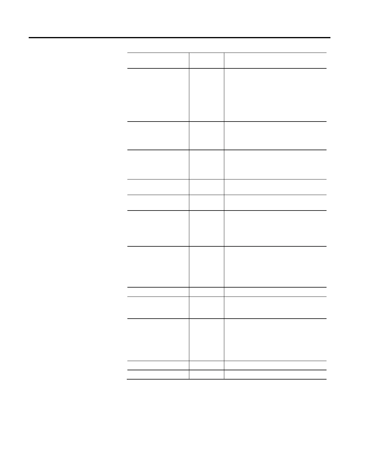
Bit Safety
Supervisor State
Description
2 = Configured (No Safety
Connection)
Idle
The safety function of drive has been initialized,
successfully completed self-testing, and has a valid safety
configuration. However, the device is not executing the
operational components of its safety functions. Configuring
and Configured are persistent states that are preserved
through power cycles.
3 = Self-Test Exception
Self-Test
Exception
The safety function of drive has detected an exception
condition during self-testing. The details of the exception
are stored in the appropriate attribute values of the Safety
Supervisor object.
4 = Running Executing
The safety function of drive is fully configured with an open
safety output connection and executing.
In this state, the drive is operational and free to apply
torque to the motor as long as there are no safety demands.
5 = Recoverable Fault Abort
The safety function of drive is in a faulted state that can be
recovered by cycling the power or reconnecting the drive.
6 = Unrecoverable Fault Critical Fault
The safety function of drive is in a faulted state for which
there is no recovery other than replacing the module.
7 = Configuring Configuring
The safety function of drive has been initialized,
successfully completed self-testing, and is in the process of
receiving a valid configuration from a safety controller.
Configuring and Id
le are persistent states that are preserved
through power cycles.
8 = Not Configured Waiting for TUNID
The safety function of drive has exited Self-testing and
recognizes that it has the out-of-box default configuration
values, for example it has not been configured by a safety
controller. The drive remains in this state until a safety
controller initiates the configuration process. Application of
torque to the motor is NOT permitted in this state.
9...50 = Reserved - -
51 = Not Configured (Torque
Permitted)
Waiting for TUNID
with Torque
Permitted
Same behavior as Not Configured state with the exception
that the drive axis is operational and the safety function
will permit application of torque to the motor.
52 = Running (Torque Permitted)
Executing with
Torque Permitted
Same behavior as Running state with the exception that
the drive axis is operational and the safety function will
permit application of torque to the motor.
Entering this state from the Running state requires a
successful STO Mode change service applied while the
safety controller is in Program Mode.
53...99 = Device Specific - -
100...255 = Vendor Specific - -

 Loading...


