EasyManuals Logo

Allen-Bradley PowerFlex 755 Reference Manual

Allen-Bradley PowerFlex 755
497 pages
To Next Page IconTo Next Page
To Previous Page IconTo Previous Page
Page #447 background imageLoading...
Page #447 background image
CIP Axis Attributes
Chapter 4
Rockwell Automation Publication MOTION-RM003I-EN-P - February 2018 447
1. Switch to Stopping state.
2. Apply "Current Decel" or "Ramp Decel" method to stop motor.
3. Wait for zero speed or 'Stopping Time Limit' or a factory set timeout,
whichever occurs first.
4. Deactivate Mechanical Brake output to engage brake.
5. Wait for "Mechanical Brake Engage Delay" while brake engages.
6. Perform (optional) Brake Proving operation to verify brake control of load.
7. Disable inverter power structure.
8. Transition to Stopped state.
9. Deactivate Resistive Brake contactor to disconnect motor from inverter
power structure.
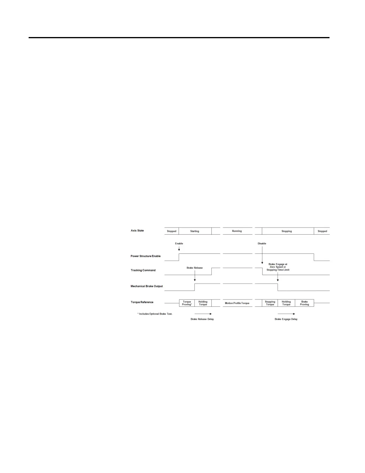
The following diagram illustrates a Category 1 Stop Sequence:
Category 2 Stop Sequence
Torque is applied to stop the motor and inverter is left enabled to provide holding
torque. The mechanical brake is not used. Brake Proving is not applicable. A
Category 2 Stop is only allowed in no Start Inhibit condition is present.
1. Switch to Stopping state.
2. Apply "Current Decel" or "Ramp Decel" method to stop motor.
3. Wait for zero speed or "Stopping Time Limit" or a factory set timeout,
whichever occurs first.

Table of Contents

Other manuals for Allen-Bradley PowerFlex 755

Questions and Answers:

Question and Answer IconNeed help?

Do you have a question about the Allen-Bradley PowerFlex 755 and is the answer not in the manual?

Allen-Bradley PowerFlex 755 Specifications

General IconGeneral
CategoryAC Drive
Amperage2.2…1470 A
Output Voltage0 to Input Voltage
Output Current2.2…1470 A
EnclosureIP20, IP30, IP54
CommunicationsEtherNet/IP, ControlNet, DeviceNet
I/ODigital, Analog, Encoder, Relay
SafetySafe Speed Monitor
Protection FeaturesOvercurrent, Overvoltage, Undervoltage, Overload, Short Circuit, Ground Fault, Overtemperature
Operating Temperature-10°C to 50°C (14°F to 122°F)
Storage Temperature-40°C to 70°C (-40°F to 158°F)
Humidity5…95% noncondensing
AltitudeUp to 1000m (3300ft) without derating
Voltage200-240V AC, 380-480V AC, 500-600V AC, 690V AC
Input Voltage200-240V AC, 380-480V AC, 500-600V AC, 690V AC
Control MethodSensorless Vector

Related product manuals