Publication 1746-UM004A-US-P
1-4 Module and Development Software Overview
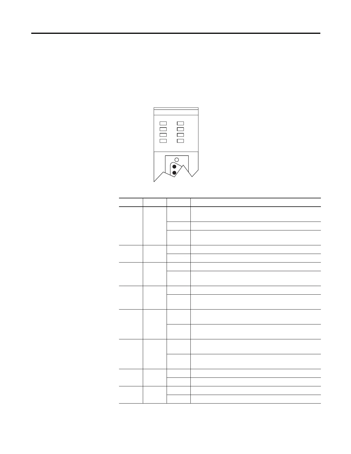
Module LEDs
There are eight LEDs on the front of the module. These LEDs are used for module
diagnostics and operator interface. The LEDs and their indications are shown on
page 1-4.
Figure 1.2 Module LEDs
Table 1.1 Module LEDs
LED Color Status Indication
ACT Green ON The module is receiving power from the backplane and is
executing BASIC code.
Blinking The module is in Command mode.
OFF The module is not receiving power from the backplane. A fault
condition exists.
485 Green ON Port DH485 on the module is active for communication.
OFF Port DH485 on the module is not active for communication.
PRT1 Green Blinking Port PRT1 on the module is transmitting or receiving signals.
OFF Port PRT1 on the module is not transmitting or receiving
signals.
PRT2 Green Blinking Port PRT2 on the module is transmitting or receiving signals.
OFF Port PRT2 on the module is not transmitting or receiving
signals.
FAULT Red ON A system problem was detected during background
diagnostics. Contact your local Allen-Bradley representative.
OFF No system problems are detected during background
diagnostics.
BA LOW Red ON The voltage of the battery that backs up RAM is low. A new
battery is needed.
OFF The voltage of the battery that backs up RAM is at an
acceptable level.
LED1 Amber ON User definable. LED activated through the user program.
OFF User definable. LED de-activated through the user program.
LED2 Amber ON User definable. LED activated through the user program.
OFF User definable. LED de-activated through the user program.
ACT
485
PR T1
PR T2
FAULT
BA LOW
LED1
LED2
BASIC